نقشه راه اندازی بوستر پمپ با اینورتر؛ از سیمکشی تا کنترل چند پمپ

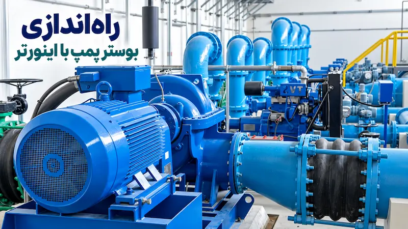
راه اندازی بوستر پمپ با اینورتر چیست و چرا استفاده میشود؟
راه اندازی بوستر پمپ با اینورتر یکی از روشهای مدرن برای کنترل فشار آب در سیستمهای آبرسانی، ساختمانهای مسکونی، مجموعههای تجاری و صنایع است. در بسیاری از این کاربردها، میزان مصرف آب در طول شبانهروز ثابت نیست و تغییرات ناگهانی مصرف میتواند باعث افت فشار، افزایش استهلاک تجهیزات و کاهش راندمان سیستم شود.
در روشهای سنتی، کنترل فشار معمولاً با روشن و خاموش شدن پمپها انجام میشود. این روش در بسیاری از پروژهها قابل استفاده است، اما در شرایطی که میزان مصرف دائماً تغییر میکند، ممکن است باعث افزایش تعداد استارتها، نوسان فشار و مصرف انرژی بیشتر شود.
در سیستمهای مجهز به اینورتر، سرعت موتور پمپ بر اساس نیاز واقعی شبکه تنظیم میشود. به این معنا که پمپ همیشه با حداکثر توان کار نمیکند، بلکه متناسب با میزان مصرف، دور موتور افزایش یا کاهش پیدا میکند تا فشار آب در محدوده مطلوب حفظ شود.
در یک بوستر پمپ دور متغیر، سنسور فشار به صورت لحظهای وضعیت شبکه را اندازهگیری کرده و اطلاعات را به اینورتر ارسال میکند. اینورتر نیز با تحلیل این دادهها و مقایسه آن با فشار تنظیمشده، سرعت موتور را کنترل میکند.
به همین دلیل، استفاده از این سیستم فقط برای افزایش فشار آب نیست؛ بلکه هدف اصلی ایجاد یک سیستم پایدار، کماستهلاک و بهینه از نظر مصرف انرژی است.
بوستر پمپ اینورتری چگونه کار میکند؟
بوستر پمپ اینورتری سیستمی است که در آن سرعت گردش الکتروموتور پمپ به کمک درایو کنترل دور تنظیم میشود. تفاوت اصلی این سیستم با بوستر پمپهای معمولی در نحوه واکنش آن به تغییرات مصرف آب است.
در بوستر پمپهای دور ثابت، زمانی که فشار کاهش پیدا میکند، معمولاً یک پمپ روشن یا خاموش میشود. اما در سیستم دور متغیر، ابتدا سرعت موتور تغییر میکند تا سیستم بتواند با نوسان کمتر، فشار مورد نیاز را تأمین کند.
فرآیند عملکرد سیستم به شکل زیر است:
افزایش مصرف آب
↓
کاهش فشار شبکه
↓
اندازهگیری فشار توسط سنسور
↓
ارسال بازخورد به اینورتر
↓
تحلیل اختلاف فشار توسط کنترلر
↓
افزایش سرعت موتور پمپ
↓
بازگشت فشار به مقدار تنظیمشده
در زمان کاهش مصرف نیز فرآیند برعکس اتفاق میافتد؛ یعنی اینورتر با کاهش سرعت موتور، میزان تولید فشار را متناسب با نیاز واقعی سیستم تنظیم میکند.
این نحوه کنترل باعث میشود پمپ در نقطه کاری مناسبتری فعالیت کند و از کارکرد غیرضروری با توان بالا جلوگیری شود.
مهمترین مزایای استفاده از اینورتر در بوستر پمپ
استفاده از اینورتر در سیستمهای بوستر پمپ میتواند مزایای مختلفی ایجاد کند، از جمله:
- حفظ فشار آب پایدار در شرایط مختلف مصرف
- کاهش تعداد خاموش و روشن شدنهای مکرر موتور
- کاهش استهلاک تجهیزات مکانیکی و الکتریکی
- بهینهسازی مصرف انرژی در زمانهای کممصرف
- کنترل دقیقتر سیستمهای چندپمپه
- افزایش عمر مفید تجهیزات
با این حال، عملکرد مناسب یک بوستر پمپ اینورتری فقط به نصب درایو وابسته نیست. انتخاب صحیح تجهیزات، تنظیم دقیق پارامترها، نصب اصولی سنسور فشار و طراحی مناسب سیستم کنترل، نقش مهمی در عملکرد نهایی مجموعه دارند.
تفاوت بوستر پمپ دور ثابت و بوستر پمپ دور متغیر
انتخاب بین سیستم دور ثابت و دور متغیر به شرایط پروژه، میزان مصرف و سطح کنترل مورد نیاز بستگی دارد.
در بوستر پمپ دور ثابت، کنترل فشار معمولاً با تغییر تعداد پمپهای فعال انجام میشود. یعنی زمانی که مصرف افزایش پیدا میکند، پمپ دیگری وارد مدار میشود.
اما در بوستر پمپ دور متغیر، علاوه بر مدیریت تعداد پمپها، سرعت هر موتور نیز قابل تنظیم است.
مقایسه کلی این دو سیستم:
| ویژگی | بوستر پمپ دور ثابت | بوستر پمپ دور متغیر |
|---|---|---|
| روش کنترل | روشن و خاموش شدن پمپ | تغییر سرعت موتور |
| کنترل فشار | محدودتر | دقیقتر |
| مصرف انرژی | بیشتر در بارهای کم | بهینهتر |
| استهلاک | بالاتر به دلیل استارت زیاد | کمتر |
| مناسب برای | پروژههای ساده | ساختمانها و صنایع با تغییر مصرف |
در پروژههایی که میزان مصرف آب در طول روز تغییر زیادی دارد، استفاده از کنترل دور موتور میتواند عملکرد سیستم را به شکل قابل توجهی بهبود دهد.
اجزای اصلی سیستم بوستر پمپ اینورتری
یک سیستم بوستر پمپ مجهز به اینورتر از چند بخش اصلی تشکیل شده است که هر کدام وظیفه مشخصی در کنترل فشار دارند.
اینورتر یا درایو کنترل دور
اینورتر بخش اصلی کنترل سیستم است. وظیفه آن تبدیل برق ورودی به خروجی با فرکانس قابل تنظیم و کنترل سرعت موتور الکتریکی است.
در کاربردهای پمپی، اینورتر باید قابلیتهایی مانند کنترل PID، دریافت سیگنال سنسور فشار، تنظیم فرکانس کاری و مدیریت شرایط حفاظتی را داشته باشد.
انتخاب اینورتر فقط بر اساس توان موتور انجام نمیشود. مواردی مانند جریان نامی موتور، نوع برق ورودی، تعداد پمپها، شرایط محیطی و نوع کاربرد نیز باید بررسی شوند.
برای مثال، در انتخاب درایو باید توجه شود که توان موتور از ظرفیت نامی درایو بیشتر نباشد؛ زیرا انتخاب اشتباه میتواند باعث کاهش عملکرد و ایجاد خطا شود.
الکتروموتور و پمپ
پمپ وظیفه ایجاد فشار و انتقال آب را دارد و موتور نیروی لازم برای چرخش آن را فراهم میکند.
اینورتر مستقیماً باعث افزایش قدرت پمپ نمیشود؛ بلکه با کنترل سرعت موتور، شرایط کاری پمپ را تنظیم میکند.
یکی از نکات مهم در اتصال موتور به اینورتر، هماهنگی نوع اتصال سیمپیچ موتور با ولتاژ خروجی درایو است. اشتباه در سربندی موتور میتواند باعث کاهش توان یا ایجاد خطای اضافه جریان شود.
سنسور فشار یا پرشر ترانسمیتر
سنسور فشار یکی از مهمترین اجزای سیستم کنترل حلقه بسته است.
این قطعه فشار واقعی آب را اندازهگیری کرده و آن را به صورت سیگنال الکتریکی به اینورتر ارسال میکند.
بدون وجود فیدبک فشار، اینورتر نمیتواند تشخیص دهد که چه زمانی باید سرعت موتور را افزایش یا کاهش دهد.
در بسیاری از سیستمها از سنسورهای ۴ تا ۲۰ میلیآمپر استفاده میشود، زیرا این نوع سیگنال مقاومت مناسبی در برابر نویز دارد و برای سیستمهای صنعتی و تأسیساتی رایج است.
راهنمای فنی درایوهای پمپی نیز بخش مستقلی برای نحوه اتصال سنسورهای ولتاژی و جریانی در نظر گرفته است.
تابلو کنترل بوستر پمپ
تابلو کنترل محل نصب تجهیزات الکتریکی، تجهیزات حفاظتی، ترمینالهای فرمان و ارتباطات سیستم است.
در یک طراحی استاندارد باید مسیر قدرت، مسیر فرمان و تجهیزات حفاظتی به شکل اصولی اجرا شوند.
محل نصب درایو نیز اهمیت زیادی دارد. نصب داخل تابلو با تهویه مناسب، جلوگیری از ورود گردوغبار، کنترل دما و رعایت فاصلههای نصب، روی عمر و عملکرد دستگاه تأثیر مستقیم دارد.
منبع تحت فشار
منبع تحت فشار باعث کاهش نوسانات لحظهای فشار و عملکرد نرمتر سیستم میشود.
این تجهیز کمک میکند در زمان مصرفهای کوتاه و لحظهای، سیستم مجبور به واکنش سریع و غیرضروری نباشد.
نقشه راه اندازی بوستر پمپ با اینورتر چگونه است؟
راه اندازی بوستر پمپ با اینورتر فقط به معنی قرار دادن یک درایو بین برق و موتور نیست. یک سیستم حرفهای باید بتواند اطلاعات وضعیت واقعی شبکه را دریافت کند، آن را تحلیل کند و بر اساس نیاز مصرفکننده، عملکرد موتور را تغییر دهد.
به همین دلیل، یک راه اندازی استاندارد شامل سه بخش اصلی است:
- مدار قدرت
- مدار فرمان و کنترل
- سیستم بازخورد فشار
در بخش قدرت، برق ورودی به اینورتر متصل میشود و خروجی اینورتر به موتور پمپ ارسال میشود. در بخش کنترل، سنسور فشار اطلاعات شبکه را اندازهگیری کرده و به درایو ارسال میکند. سپس کنترلر داخلی اینورتر بر اساس مقدار فشار تنظیمشده، سرعت موتور را تغییر میدهد.
در راهنمای نصب درایوهای پمپی، بخش نصب الکتریکی شامل شماتیک کلی اتصال درایو، الکتروپمپ و تجهیزات مرتبط است و تأکید شده که ترمینالهای قدرت و فرمان باید مطابق نقشه سیمبندی صحیح متصل شوند.
اتصال برق و موتور در بوستر پمپ اینورتری
اولین مرحله در راه اندازی، اتصال صحیح موتور به خروجی اینورتر است.
در این مرحله باید چند نکته مهم بررسی شود:
- توان موتور با ظرفیت اینورتر هماهنگ باشد
- جریان نامی موتور از محدوده مجاز درایو بیشتر نباشد
- نوع برق ورودی با مشخصات موتور و درایو سازگار باشد
- سربندی موتور به صورت صحیح انجام شود
یکی از اشتباهات رایج در نصب بوستر پمپ با اینورتر، انتخاب درایو فقط بر اساس توان موتور است. در حالی که جریان نامی موتور، شرایط کاری پمپ و نحوه استفاده از سیستم اهمیت زیادی دارد.
برای مثال، ممکن است دو موتور با توان یکسان، جریان کاری متفاوتی داشته باشند و انتخاب درایو فقط بر اساس عدد کیلووات باعث انتخاب نادرست شود.
اتصال سنسور فشار به اینورتر
سنسور فشار نقش چشم سیستم کنترل را دارد.
این سنسور روی خط خروجی آب نصب میشود و فشار واقعی شبکه را اندازهگیری میکند. سپس این مقدار به ورودی آنالوگ یا ورودی مخصوص سنسور درایو ارسال میشود.
اینورتر با مقایسه دو مقدار:
- فشار واقعی سیستم
- فشار هدف تنظیمشده
تصمیم میگیرد که سرعت موتور افزایش یا کاهش پیدا کند.
به عنوان مثال:
اگر فشار مورد نیاز ۴ بار تنظیم شده باشد و مصرف آب باعث کاهش فشار به ۳.۵ بار شود، کنترلر فرمان افزایش سرعت موتور را صادر میکند تا فشار دوباره به مقدار هدف برسد.
تنظیم فشار هدف یا Setpoint
یکی از مهمترین تنظیمات درایو برای بوستر پمپ، تعیین مقدار فشار مطلوب است.
این مقدار باید بر اساس نیاز واقعی سیستم انتخاب شود، نه صرفاً بر اساس حداکثر توان پمپ.
تنظیم بیش از حد فشار میتواند باعث:
- مصرف انرژی بیشتر
- افزایش استهلاک تجهیزات
- فشار اضافی روی لولهکشی و اتصالات
شود.
در مقابل، تنظیم پایینتر از نیاز واقعی باعث افت کیفیت مصرف و نارضایتی کاربران خواهد شد.
کنترل فشار بوستر پمپ با PID چگونه انجام میشود؟
یکی از مهمترین مفاهیم در راه اندازی بوستر پمپ با اینورتر، کنترل PID است.
میتوان گفت PID یک الگوریتم کنترلی است که باعث میشود تغییرات سرعت موتور به صورت نرم و دقیق انجام شود.
بدون تنظیم مناسب PID، ممکن است سیستم با مشکلاتی مانند:
- نوسان فشار
- افزایش و کاهش سریع دور موتور
- تأخیر در پاسخ سیستم
- روشن و خاموش شدنهای غیرضروری
مواجه شود.
کنترل PID از سه بخش تشکیل شده است:
بخش تناسبی یا Proportional
این بخش میزان اختلاف بین فشار واقعی و فشار هدف را بررسی میکند.
هرچه اختلاف بیشتر باشد، واکنش سیستم بیشتر خواهد بود.
بخش انتگرالی یا Integral
این بخش خطاهای باقیمانده در طول زمان را اصلاح میکند.
برای مثال اگر سیستم همیشه کمی پایینتر از فشار تنظیمشده کار کند، بخش انتگرالی این اختلاف را جبران میکند.
بخش مشتقی یا Derivative
این قسمت سرعت تغییرات فشار را بررسی میکند و کمک میکند سیستم واکنش کنترلشدهتری داشته باشد.
در کاربردهای واقعی بوستر پمپ، هدف PID این نیست که موتور دائم تغییر سرعت دهد؛ بلکه هدف رسیدن به یک نقطه پایدار با کمترین نوسان است.
کنترل چند پمپ با اینورتر چگونه انجام میشود؟
در ساختمانهای بزرگ، صنایع و سیستمهایی که مصرف آب متغیر دارند، معمولاً یک پمپ به تنهایی پاسخگوی نیاز نیست.
در این شرایط از سیستم بوستر پمپ چندپمپه استفاده میشود.
کنترل چند پمپ با اینورتر معمولاً به چند روش انجام میشود:
روش اول: هر پمپ با یک اینورتر مستقل
در این روش، هر الکتروپمپ دارای یک درایو جداگانه است.
مزایای این روش:
- کنترل دقیقتر هر موتور
- کاهش فشار روی تجهیزات
- امکان مدیریت بهتر ظرفیت سیستم
در سیستمهای حرفهای، ارتباط بین درایوها میتواند برای هماهنگی عملکرد پمپها استفاده شود.
روش دوم: یک اینورتر برای چند پمپ
در برخی پروژهها، یک درایو وظیفه کنترل یک پمپ اصلی را دارد و پمپهای دیگر بر اساس نیاز وارد مدار میشوند.
این روش میتواند هزینه اولیه را کاهش دهد، اما طراحی کنترل و تابلو اهمیت بیشتری پیدا میکند.
روش سوم: سیستم ترکیبی
در این روش ترکیبی از پمپ دور متغیر و پمپهای دور ثابت استفاده میشود.
برای مثال:
- پمپ اول با اینورتر سرعت خود را تغییر میدهد
- در صورت افزایش مصرف، پمپهای کمکی وارد مدار میشوند
این روش در بسیاری از سیستمهای بوستر پمپ کاربرد دارد زیرا تعادل مناسبی بین هزینه و عملکرد ایجاد میکند.
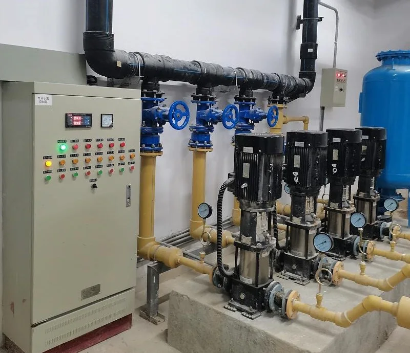
متسر اسلیو (Master Slave) در بوستر پمپ چیست؟
در سیستمهای چند اینورتری، یکی از روشهای رایج مدیریت پمپها استفاده از ساختار Master Slave است.
در این روش:
- یک درایو به عنوان Master وظیفه مدیریت سیستم را بر عهده میگیرد
- سایر درایوها به عنوان Slave از فرمانها پیروی میکنند
در واقع Master معمولاً اطلاعات فشار، میزان مصرف و وضعیت سایر پمپها را بررسی میکند و تصمیم میگیرد کدام پمپ فعال باشد.
مزیت این روش، هماهنگی بهتر بین پمپها و جلوگیری از عملکرد نامنظم سیستم است.
تنظیم اینورتر بوستر پمپ: تنظیمات مهم اینورتر برای بوستر پمپ چیست؟
پس از نصب سختافزاری، تنظیمات نرمافزاری اهمیت زیادی دارد.
مهمترین پارامترها عبارتاند از:
مشخصات موتور
شامل:
- توان موتور
- جریان نامی
- ولتاژ موتور
- فرکانس کاری
این اطلاعات معمولاً از پلاک موتور استخراج میشوند.
تنظیم ورودی سنسور فشار
نوع سنسور، محدوده اندازهگیری و نوع سیگنال باید به درستی تنظیم شود.
اشتباه در این مرحله میتواند باعث شود مقدار فشار نمایش دادهشده با مقدار واقعی تفاوت داشته باشد.
حداقل و حداکثر فرکانس
این تنظیم مشخص میکند موتور در چه محدودهای اجازه تغییر سرعت دارد.
تنظیم نادرست این بخش میتواند باعث:
- کارکرد بیش از حد موتور
- کاهش راندمان
- ایجاد مشکل در سیستم مکانیکی
شود.
زمان شتاب و کاهش سرعت
اگر زمان افزایش یا کاهش سرعت خیلی کوتاه باشد، ممکن است فشار شبکه دچار تغییر ناگهانی شود.
تنظیم مناسب Ramp Up و Ramp Down باعث عملکرد نرمتر سیستم خواهد شد.
مشکلات رایج در راه اندازی بوستر پمپ با اینورتر
حتی در سیستمهای طراحیشده مناسب، برخی مشکلات در زمان نصب یا تنظیم ممکن است رخ دهد.
| مشکل | علت احتمالی | موارد بررسی |
|---|---|---|
| فشار آب نوسان دارد | تنظیم PID یا مشکل سنسور | بررسی پارامترهای کنترل و Feedback |
| پمپ دوم وارد مدار نمیشود | تنظیمات مرحلهبندی | بررسی Stage و Delay |
| همه پمپها همزمان روشن میشوند | مشکل Sequencing | بررسی Master و Slave |
| پمپ دائماً روشن است | تنظیم نبودن Sleep Mode | بررسی حداقل فرکانس و No Flow |
| مقدار فشار اشتباه نمایش داده میشود | مشکل Scaling سنسور | بررسی سیگنال 4 تا 20 میلیآمپر |
علت نوسان فشار در بوستر پمپ چیست؟
چند عامل میتواند باعث نوسان فشار شود:
- تنظیم نبودن PID
- انتخاب نامناسب سنسور فشار
- نصب اشتباه سنسور
- تنظیم نادرست فشار هدف
- انتخاب اشتباه ظرفیت پمپ
قبل از تغییر پارامترها باید مشخص شود مشکل از طراحی سیستم است یا تنظیمات کنترل.
چگونه اینورتر مناسب بوستر پمپ انتخاب کنیم؟
انتخاب اینورتر برای پمپ یکی از مهمترین مراحل طراحی سیستم است.
برای انتخاب صحیح باید موارد زیر بررسی شوند:
توان و جریان موتور
اولین معیار، مشخصات واقعی موتور است.
درایو باید توانایی تحمل جریان کاری موتور را داشته باشد.
نوع کاربرد
اینورترهای عمومی ممکن است برای بسیاری از موتورها مناسب باشند، اما کاربرد درایو پمپی نیازمند امکانات کنترلی خاص مانند PID و مدیریت فشار است.
تعداد پمپها
سیستم تکپمپه و چندپمپه نیازهای متفاوتی دارند.
شرایط محیط نصب
دمای محیط، تهویه تابلو، رطوبت و گردوغبار روی انتخاب و عمر تجهیزات تأثیر دارند.
طبق راهنمای نصب درایوهای پمپی، محل نصب باید دارای تهویه مناسب باشد و شرایط محیطی مانند دما و رطوبت در محدوده مجاز رعایت شود.
آیا هر اینورتری برای بوستر پمپ مناسب است؟
خیر.
هرچند از نظر فنی بسیاری از اینورترها میتوانند سرعت موتور را کنترل کنند، اما کاربرد بوستر پمپ نیازمند قابلیتهایی فراتر از تغییر سرعت است.
یک سیستم مناسب باید بتواند:
- فشار را کنترل کند
- از بازخورد سنسور استفاده کند
- تغییرات مصرف را مدیریت کند
- شرایط غیرعادی مانند اضافه بار را تشخیص دهد
- با ساختار چندپمپه هماهنگ شود
به همین دلیل، استفاده از درایوی که برای کاربردهای پمپی طراحی شده، معمولاً نتیجه قابل اطمینانتری ایجاد میکند.
سوالات متداول درباره راه اندازی بوستر پمپ با اینورتر
راه اندازی بوستر پمپ با اینورتر شامل چندین بخش فنی مانند انتخاب تجهیزات، اتصال صحیح، تنظیم پارامترها و هماهنگی بین پمپ و سیستم کنترل است. در ادامه به رایجترین سوالاتی که هنگام طراحی، نصب و استفاده از بوستر پمپهای اینورتری مطرح میشود پاسخ میدهیم.
آیا میتوان هر پمپی را به اینورتر متصل کرد؟
باید مشخصات موتور، توان، جریان و شرایط کاری بررسی شود. هر موتور الزاماً برای هر شرایط کنترلی مناسب نیست.
سنسور فشار بوستر پمپ کجا نصب میشود؟
معمولاً سنسور روی خط خروجی مشترک بوستر پمپ نصب میشود تا فشار واقعی شبکه را اندازهگیری کند.
کنترل PID در بوستر پمپ چه کاربردی دارد؟
در واقع PID باعث میشود تغییر سرعت موتور نرمتر و دقیقتر انجام شود و فشار در مقدار هدف ثابتتر باقی بماند.
چند پمپ را میتوان با یک اینورتر کنترل کرد؟
بسته به طراحی سیستم، نوع کنترلر و ظرفیت تجهیزات متفاوت است. تعداد پمپها باید بر اساس توان درایو و معماری کنترل تعیین شود.
چرا فشار بوستر پمپ ثابت نمیماند؟
دلایل رایج شامل تنظیم نبودن PID، مشکل سنسور فشار، انتخاب نادرست تجهیزات یا تنظیم اشتباه پارامترها است.
جمعبندی
راه اندازی بوستر پمپ با اینورتر یکی از روشهای موثر برای ایجاد فشار ثابت، کاهش مصرف انرژی و افزایش عمر تجهیزات در سیستمهای آبرسانی است.
اما موفقیت این سیستم فقط به خرید یک اینورتر وابسته نیست. طراحی درست، انتخاب مناسب تجهیزات، نصب اصولی، تنظیم دقیق پارامترها و تست نهایی همگی در عملکرد نهایی تأثیر دارند.
یک سیستم بوستر پمپ حرفهای باید بتواند خود را با تغییرات مصرف هماهنگ کند و بدون ایجاد نوسان، فشار مورد نیاز را در اختیار مصرفکننده قرار دهد.
به همین دلیل، قبل از انتخاب تجهیزات یا شروع نصب، بررسی شرایط پروژه و استفاده از مستندات فنی معتبر میتواند از بسیاری از مشکلات آینده جلوگیری کند.
How to Set Up a Booster Pump with an Inverter?
Setting up a booster pump with an inverter is one of the most effective solutions for maintaining stable water pressure in residential buildings, commercial complexes, industrial facilities, and water supply systems.
In many applications, water demand is not constant throughout the day. During low-consumption periods, only a small amount of water may be required, while during peak hours, multiple users may consume water simultaneously. These continuous changes in demand can cause pressure fluctuations, unnecessary pump operation, higher energy consumption, and increased equipment wear.
Traditional booster pump systems usually control pressure by switching pumps on and off. Although this method is still widely used, it can create several challenges, including frequent motor starts, pressure variations, mechanical stress, and inefficient energy usage.
A booster pump with an inverter provides a more advanced approach by adjusting the pump motor speed according to the actual system demand. Instead of operating the pump at maximum capacity all the time, the inverter increases or decreases the motor speed to maintain the required pressure level.
In an inverter-based booster pump system, a pressure sensor continuously monitors the water pressure and sends feedback to the inverter. The inverter analyzes this information and adjusts the pump motor speed to keep the pressure close to the desired setpoint.
The main purpose of using an inverter in a booster pump system is not only increasing water pressure but also creating a more stable, efficient, and reliable pumping solution.
How Does a Booster Pump with an Inverter Work?
A booster pump with an inverter is a system where the speed of the pump motor is controlled according to changes in water demand.
The main difference between a conventional booster pump and an inverter-based system is the way they respond to pressure changes.
In a fixed-speed booster pump system, pressure control is usually achieved by turning pumps on or off. When demand increases and pressure drops, an additional pump may start operating to compensate for the pressure loss.
However, in a variable-speed booster pump system, the first response is changing the motor speed. The inverter adjusts the pump operation smoothly to maintain the required pressure with fewer fluctuations.
Booster Pump Inverter Operation Process
The control process works as follows:
Increase in water consumption
↓
Decrease in network pressure
↓
Pressure measurement by the sensor
↓
Feedback signal sent to the inverter
↓
Controller analyzes the pressure difference
↓
Pump motor speed increases
↓
Pressure returns to the set value
When water consumption decreases, the inverter reduces the motor speed to match the actual demand of the system.
This control method allows the pump to operate closer to its optimal working condition and prevents unnecessary high-power operation.
Benefits of Using an Inverter in a Booster Pump System
Using an inverter in a pump system provides several important advantages:
Constant Water Pressure
One of the main benefits of a pump inverter is maintaining stable water pressure despite changes in consumption.
This is especially important in:
- Residential buildings
- Hotels
- Hospitals
- Commercial complexes
- Industrial facilities
Reduced Pump Wear
Frequent start and stop cycles can increase mechanical stress on pumps and motors.
By controlling motor speed smoothly, an inverter reduces unnecessary starts and helps extend equipment lifetime.
Lower Energy Consumption
A pump does not always need to operate at full capacity. During low-demand periods, reducing motor speed can significantly improve energy efficiency.
Better Multi-Pump Management
Inverter-based systems provide more accurate control for applications where multiple pumps operate together.
Improved System Reliability
A properly designed booster pump system with an inverter can provide more stable operation, fewer pressure fluctuations, and better overall performance.
However, achieving these benefits depends on proper equipment selection, correct installation, accurate parameter settings, and suitable system design.
Fixed Speed Booster Pump vs Variable Speed Booster Pump
Choosing between a fixed-speed and variable-speed booster pump depends on the project requirements, water consumption pattern, and required level of control.
Fixed Speed Booster Pump
In a fixed-speed system, pumps operate at a constant speed. Pressure control is usually performed by switching pumps on or off according to demand.
Advantages:
- Simple design
- Lower initial cost
- Suitable for basic applications
Disadvantages:
- More frequent starts and stops
- Higher mechanical stress
- Less accurate pressure control
- Higher energy consumption during low-demand conditions
Variable Speed Booster Pump with Inverter
In an inverter-based system, the motor speed changes according to the actual pressure requirements.
Advantages:
- More stable pressure control
- Lower energy consumption
- Reduced mechanical stress
- Better response to consumption changes
- Improved control of multi-pump systems
The comparison can be summarized as follows:
| Feature | Fixed Speed Booster Pump | Booster Pump with Inverter |
|---|---|---|
| Control method | Pump start/stop control | Motor speed adjustment |
| Pressure stability | Limited | More accurate |
| Energy efficiency | Lower | Higher |
| Motor stress | Higher | Lower |
| Suitable applications | Simple projects | Buildings and systems with variable demand |
For systems where water consumption changes significantly throughout the day, using an inverter can greatly improve overall performance.
Main Components of an Inverter-Based Booster Pump System
A booster pump system with an inverter consists of several important components. Each part has a specific role in maintaining pressure control and system stability.
Pump Inverter
The inverter is the main control component of the system.
Its primary function is to control the speed of the pump motor according to system requirements.
For pump applications, the inverter should support functions such as:
- Pressure control
- Sensor feedback
- Motor speed adjustment
- Protection functions
- Pump-specific control parameters
Selecting an inverter should not be based only on motor power. Other factors such as motor current, input power supply, number of pumps, installation conditions, and application type should also be considered.
Pump and Motor
The pump is responsible for creating water pressure and transferring water through the system.
The inverter does not directly increase pump power. Instead, it controls motor speed to optimize pump operation according to demand.
Proper matching between the pump motor specifications and inverter capacity is essential for reliable operation.
Pressure Sensor
The pressure sensor is one of the most important components in a closed-loop control system.
It measures the actual water pressure and sends feedback information to the inverter.
Without pressure feedback, the inverter cannot determine whether motor speed should increase or decrease.
Common pressure sensors used in these systems provide standard signals such as 4–20 mA, which are widely used in industrial and building automation applications.
Booster Pump Control Panel
The control panel contains electrical components, protection equipment, control terminals, and system communication elements.
A properly designed control panel should separate:
- Power circuits
- Control circuits
- Protection components
Correct installation conditions, proper ventilation, temperature control, and protection from dust and moisture are important factors affecting inverter performance and lifetime.
Pressure Tank
A pressure tank helps reduce sudden pressure changes and improves system stability.
It also prevents unnecessary pump reactions during short and temporary consumption changes.
Booster Pump Inverter Installation Guide
Setting up a booster pump with an inverter is not only about connecting the inverter between the power supply and the pump motor. A professional installation requires proper design of the power circuit, control circuit, and pressure feedback system.
A standard booster pump inverter setup consists of three main sections:
- Power connection
- Control and command circuit
- Pressure feedback system
In the power section, the incoming electrical supply is connected to the inverter, and the inverter output is connected to the pump motor.
In the control section, the pressure sensor measures the actual pressure of the water network and sends feedback information to the inverter. Based on the difference between the actual pressure and the set pressure value, the inverter adjusts the motor speed.
Connecting the Pump Motor to the Inverter
The first step in a booster pump inverter setup is connecting the pump motor correctly.
Several important factors must be considered during this process:
- The motor power must match the inverter capacity
- The motor rated current must be within the inverter’s operating range
- The electrical supply must be compatible with the motor and inverter specifications
- The motor wiring connection must be properly configured
One common mistake in pump inverter installation is selecting an inverter only based on motor power. Motor current, pump operating conditions, and the actual application requirements are also important factors.
Two motors with the same power rating may have different current requirements, which means inverter selection should not rely only on the kilowatt value.
Connecting the Pressure Sensor to the Inverter
The pressure sensor is the main feedback element in an inverter-based booster pump system.
It is usually installed on the common water outlet line of the booster pump system. The sensor measures the actual pressure and sends the signal to the inverter through an analog input or a dedicated sensor input.
The inverter compares two values:
- Actual system pressure
- Desired pressure setpoint
Based on this comparison, the inverter decides whether the pump motor speed should increase or decrease.
For example:
If the required pressure is set to 4 bar and water consumption causes the pressure to drop to 3.5 bar, the inverter increases the motor speed to compensate for the pressure loss and return the system pressure to the desired level.
Setting the Pressure Setpoint in a Pump Inverter
The pressure setpoint is one of the most important parameters in a booster pump system.
This value should be selected according to the actual requirements of the application, not only based on the maximum pump capacity.
Setting the pressure too high can cause:
- Higher energy consumption
- Increased equipment stress
- Additional pressure on pipes and fittings
On the other hand, setting the pressure too low can result in insufficient water supply and reduced user satisfaction.
A correct pressure setting helps the system achieve a balance between performance, energy efficiency, and equipment lifetime.
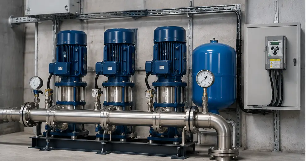
How Does PID Control Work in a Booster Pump with an Inverter?
One of the most important concepts in a booster pump inverter setup is PID control.
PID is a control algorithm that allows the inverter to adjust motor speed smoothly and accurately to maintain stable pressure.
Without proper PID adjustment, the system may experience problems such as:
- Pressure fluctuations
- Rapid motor speed changes
- Slow response to demand changes
- Unnecessary pump operation
PID control consists of three main parts:
Proportional Control (P)
The proportional section evaluates the difference between the actual pressure and the desired pressure.
The larger the pressure difference, the stronger the system response will be.
Integral Control (I)
The integral section corrects remaining errors over time.
For example, if the system continuously operates slightly below the desired pressure, the integral function gradually compensates for this difference.
Derivative Control (D)
The derivative section monitors the rate of pressure changes and helps create a more stable response.
In real booster pump applications, the goal of PID control is not to constantly change motor speed. The goal is to reach a stable operating point with minimum pressure fluctuation.
How to Control Multiple Pumps with an Inverter?
In large buildings, industrial facilities, and systems with variable water demand, a single pump may not be enough to meet the required flow rate.
For these applications, multi-pump booster systems are commonly used.
There are several methods for controlling multiple pumps with inverters:
Method 1: One Inverter for Each Pump
In this method, each pump has its own inverter.
Advantages include:
- More accurate control of each motor
- Better system management
- Improved load distribution between pumps
This method is commonly used in professional booster pump systems where precise control is required.
Method 2: One Inverter for Multiple Pumps
In some applications, one inverter controls the main pump while additional pumps are activated according to demand.
This method can reduce initial costs, but the control system design becomes more important.
Proper sequencing and communication between pumps are required to prevent unstable operation.
Method 3: Combined Variable Speed and Fixed Speed Pumps
In this method, a combination of variable-speed and fixed-speed pumps is used.
For example:
- The first pump operates with an inverter and adjusts its speed according to pressure demand
- Additional pumps start when water consumption increases
This approach provides a balance between investment cost and system performance.
What Is Master-Slave Control in a Booster Pump System?
In multi-inverter booster pump systems, one common control method is the Master-Slave structure.
In this configuration:
- One inverter operates as the Master and manages the system
- Other inverters operate as Slaves and follow the commands from the Master
The Master inverter typically monitors:
- System pressure
- Water demand
- Pump operating status
Then it determines which pumps should operate and how they should work together.
The main advantage of this method is better coordination between pumps and more stable system
محصولات
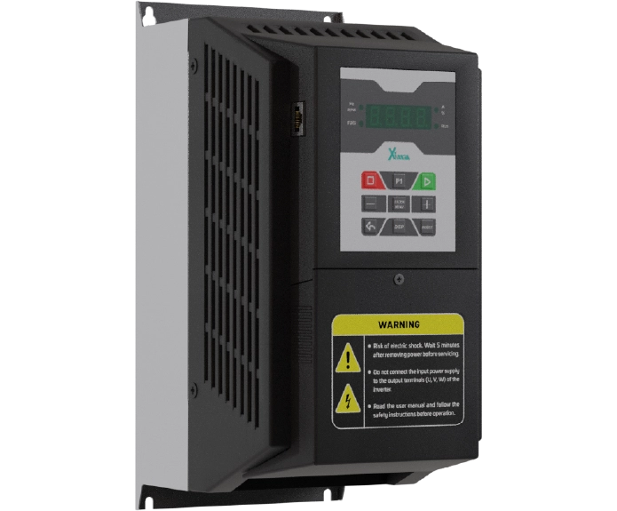
اینورتر 15 کیلووات سه فاز سری پمپ و بوستر پمپ
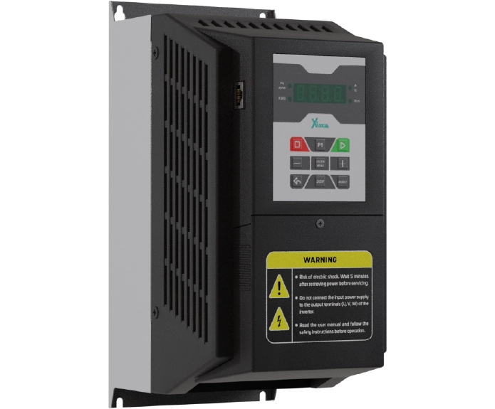
اینورتر 11 کیلووات سه فاز سری پمپ و بوستر پمپ
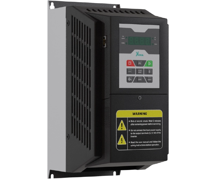
اینورتر 7.5 کیلووات سه فاز سری پمپ و بوستر پمپ
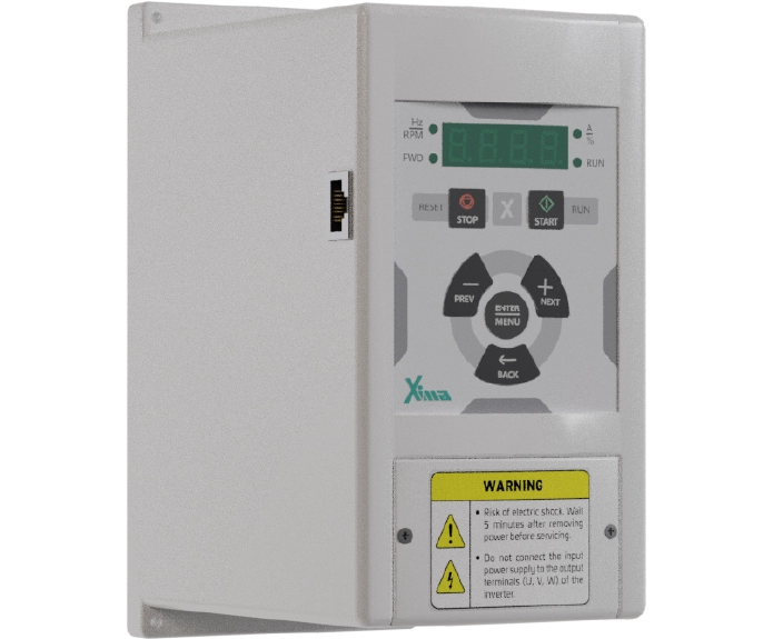
اینورتر 5.5 کیلووات سه فاز سری پمپ و بوستر پمپ
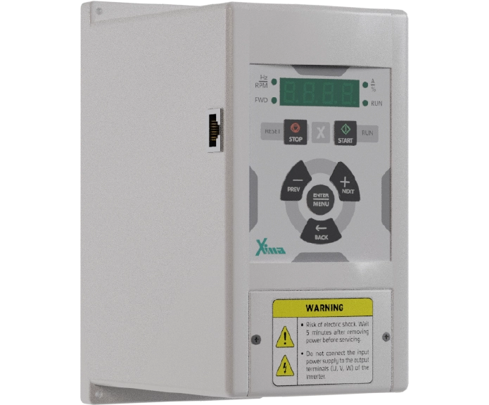
اینورتر 4 کیلووات سه فاز سری پمپ و بوستر پمپ
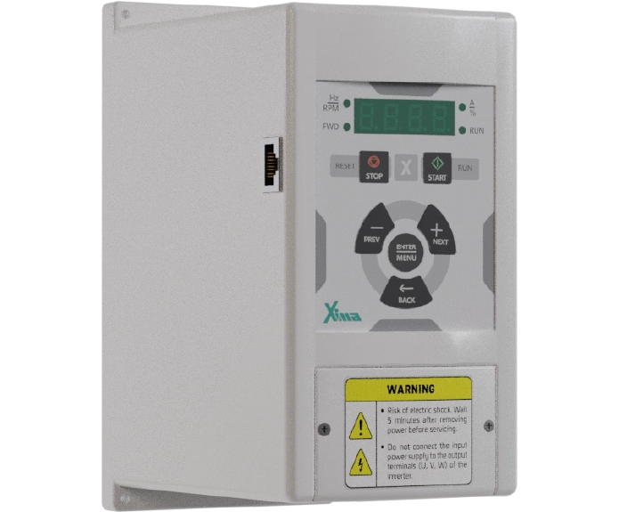
اینورتر 3 کیلووات سه فاز سری پمپ و بوستر پمپ
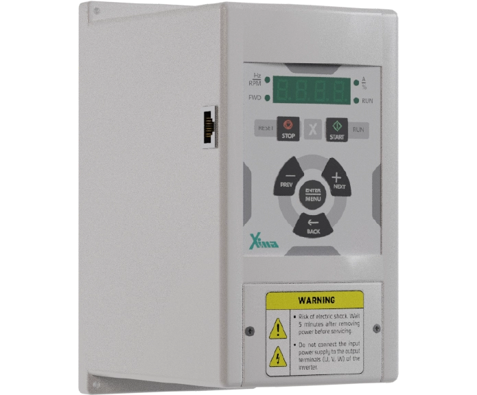
اینورتر 2.2 کیلووات سه فاز سری پمپ و بوستر پمپ
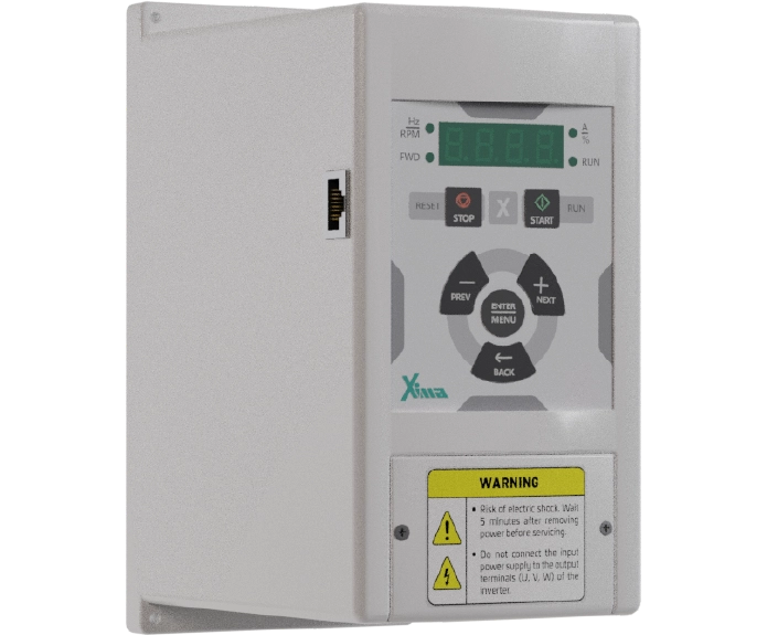
اینورتر 1.5 کیلووات سه فاز سری پمپ و بوستر پمپ
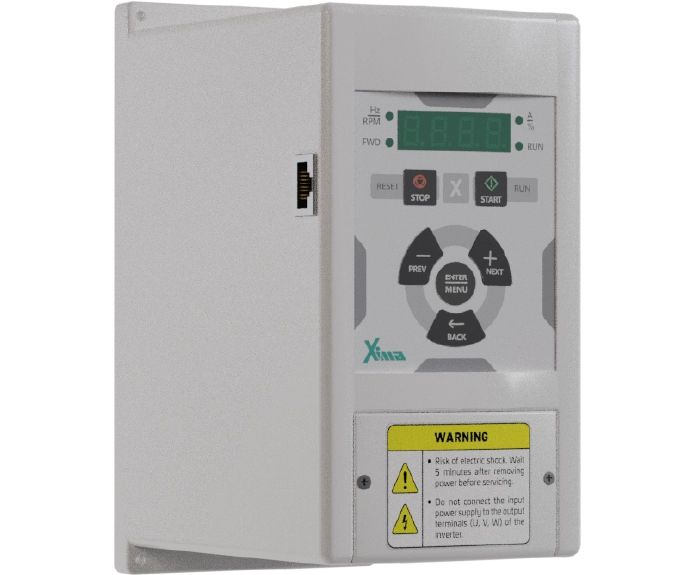
اینورتر 0.75 کیلووات سه فاز سری پمپ و بوستر پمپ
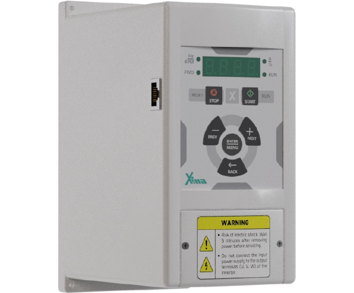
اینورتر 3 کیلووات تک فاز سری پمپ و بوستر پمپ
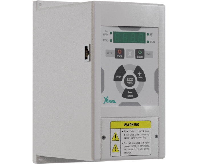
اینورتر 2.2 کیلووات تک فاز سری پمپ و بوستر پمپ
نظرات کاربران
دیدگاهها
هنوز دیدگاهی ثبت نشده است.