لیست خطاهای درایو زیما؛ سری صنعتی، پمپی، سولار پمپ و بالابر

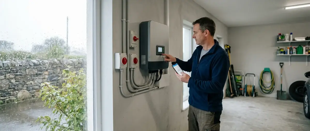
لیست خطاهای درایو زیما؛ ابتدا کد خطا و سری دستگاه را مشخص کنید
برای استفاده درست از لیست خطاهای درایو زیما، سه اطلاعات را کنار هم قرار دهید: کد روی نمایشگر، مدل دستگاه و زمان وقوع خطا. برای مثال، اضافهجریان هنگام شروع حرکت با اضافهجریان هنگام توقف، مسیر بررسی یکسانی ندارد؛ همچنین خطای سنسور در درایو پمپی با خطای سنسور دمای خود درایو متفاوت است.
نکته مهم: علتهای درجشده در جدولها «علت احتمالی» هستند. مشاهده یک کد، بهتنهایی خرابی قطعی موتور، برد یا درایو را ثابت نمیکند.
بررسی سیمکشی، موتور، مقاومت ترمز و اجزای داخلی باید توسط فرد متخصص و پس از ایمنسازی دستگاه انجام شود. خاموش شدن نمایشگر بهتنهایی اثبات بیبرقی نیست. در آسانسور و بالابر، مدار ایمنی، کنتاکتور و فیدبک ترمز را برای حذف خطا بیاثر نکنید.
جدول خطاهای مشترک درایوهای زیما
کدهای این جدول در اسناد صنعتی، پمپی، سولار و جدولهای L100 و L200 دیده میشوند. شکل بعضی حروف در نمایشگر سگمنتی با نگارش تایپی متفاوت است؛ کد را با دفترچه مدل خود تطبیق دهید.
| کد خطا | معنی | علتها | اقدام پیشنهادی |
|---|---|---|---|
SC |
اتصال کوتاه | اتصال کوتاه در خروجیها یا خرابی بخش قدرت | بررسی مسیر خروجی، موتور و بخش قدرت |
OC |
اضافهجریان |
بار زیاد، شتاب زیاد، خرابی موتور،
تنظیم اشتباه مشخصات موتور یا زیاد بودن
Pr05
|
بررسی بار، موتور و پارامترهای مرتبط |
OC-A |
اضافهجریان هنگام شتابگیری | کم بودن زمان راهاندازی |
بررسی زمان راهاندازی
Pr03
و حالت شتابگیری
|
OC-D |
اضافهجریان هنگام توقف | کم بودن زمان توقف؛ کم بودن مقدار یا اتصال کوتاه مقاومت ترمز |
بررسی
Pr04،
نحوه کاهش سرعت و مقاومت ترمز
|
Ov-D |
اضافهولتاژ هنگام توقف | کاهش سرعت شدید؛ قطع یا خرابی مقاومت ترمز | بررسی زمان توقف و مجموعه ترمز |
Ov |
اضافهولتاژ در حالت عادی | بالا بودن ولتاژ ورودی یا ورود موتور به حالت ژنراتوری بر اثر بار مکانیکی | بررسی ولتاژ ورودی و شرایط ترمز |
12oc |
خطای ترمینال ۱۲ ولت |
اتصال کوتاه یا جریانکشی بیش از حد
از ۱۲ ولت به
COM؛
خرابی فن
|
بررسی سیمکشی ترمینالها و سلامت فن |
PLoS |
قطع فاز ورودی | قطع یکی از فازها در دستگاههای ۳۸۰ ولت؛ نامتعادل بودن شدید فازهای ورودی | بررسی برق ورودی؛ در صورت نیاز بررسی خازنهای دستگاه |
Olos |
قطع فاز خروجی | نامتقارن بودن جریان موتور؛ احتمال خرابی طبقه قدرت | بررسی موتور، اتصالات و بخش قدرت |
Uv |
کمبود ولتاژ | پایین بودن ولتاژ ورودی؛ خرابی خازنهای قدرت | بررسی برق ورودی و سپس بخش قدرت |
OL |
اضافهبار | بار بیش از حد روی موتور | بررسی بار مکانیکی و تنظیمات اضافهبار |
OH |
داغ شدن دستگاه | دمای محیط، فرکانس سوئیچینگ بالا، خرابی فن، بار زیاد، مجاورت با گرما یا آلودگی هیتسینک | بررسی خنککاری، شرایط نصب و بار |
UH |
سرمای بیش از حد یا قطع سنسور حرارت | محیط بسیار سرد یا قطع سنسور | بررسی دمای واقعی و سنسور حرارت |
OP |
ناکافی بودن توان دستگاه | کم بودن توان درایو نسبت به نیاز کاربرد | بررسی انتخاب توان دستگاه |
BrOL |
بار بیش از حد روی مقاومت ترمز | کافی نبودن توان مقاومت برای کاربرد | بررسی و انتخاب مقاومت ترمز مناسب |
AUto |
خطای تنظیم اتوماتیک | نامتناسب بودن توان موتور یا قطع بودن کابل موتور | بررسی تناسب موتور و اتصال کابل |
Eflt |
خطای خارجی | فعال شدن خطای خارجی تعریفشده | بررسی منبع خطای خارجی و پارامترهای ورودیوخروجی |
HArd |
خطای سختافزار | مشکل سختافزاری پردازنده | ارجاع درایو به خدمات فنی |
triP |
خطای اضافهجریان | فعال شدن حفاظت مربوطه |
بررسی
PF09
و
PF10
مطابق دفترچه همان مدل
|
tSnS |
خطای سنسور دمای درایو | خرابی سنسور دما | ارجاع دستگاه به خدمات فنی |
خطای SC درایو زیما؛ اتصال کوتاه در کدام بخش رخ داده است؟
در مستندات زیما، برای خطای SC دو علت اصلی ذکر شده است:
- اتصال کوتاه در خروجیها؛
- خرابی بخش قدرت دستگاه.
بنابراین عیبیابی باید بین مسیر خروجی، کابل و موتور و خود درایو تفکیک ایجاد کند.
در جدول خطاها آمده است که اگر با جدا بودن سیمهای خروجی، خطا همچنان رخ دهد، دستگاه معیوب است. این بررسی، مرحلهای از سرویس تخصصی است؛ نباید آن را بهصورت قطع و وصل کابل موتور در حالت برقدار انجام داد.
اقدام درست: ثبت کد، متوقف کردن ریستهای تکراری و بررسی تخصصی مسیر خروجی.
برداشت نادرست: نتیجهگیری فوری درباره سوختن موتور یا تلاش برای رفع SC با تغییر تصادفی زمان شتاب.
تفاوت خطاهای OC، OC-A، OC-D و OL چیست؟
این کدها همگی با جریان یا بار ارتباط دارند، اما نباید بهجای یکدیگر تفسیر شوند.
| کد | نکته تعیینکننده | محور بررسی |
|---|---|---|
OC
|
اضافهجریان | بار، موتور، شتابها و تنظیمات موتور |
OC-A
|
اضافهجریان هنگام شتابگیری | زمان راهاندازی و شکل شتابگیری |
OC-D
|
اضافهجریان هنگام توقف | زمان توقف و مقاومت ترمز |
OL
|
اضافهبار | بار مکانیکی و حفاظت اضافهبار |
خطای OC؛ فقط موتور را متهم نکنید
در جدول زیما، خرابی موتور تنها یکی از علتهای OC است. بار زیاد، شتاب زیاد، تنظیم اشتباه مشخصات موتور و زیاد بودن Pr05 نیز ذکر شدهاند.
برای بررسی، این پرسشها باید پاسخ داده شوند:
- آیا خطا پس از تغییر بار ایجاد شده است؟
- آیا مشخصات موتور مطابق پلاک آن وارد شدهاند؟
- آیا زمان راهاندازی یا توقف اخیراً تغییر کرده است؟
- آیا خطا در یک مرحله مشخص از حرکت تکرار میشود؟
مستندات برای باقی ماندن OC پس از جدا کردن موتور نیز احتمال معیوب بودن دستگاه را مطرح میکنند؛ این آزمون باید در فرایند سرویس تخصصی انجام شود.
خطای OC-A؛ زمان راهاندازی را بررسی کنید
در OC-A، کم بودن زمان راهاندازی Pr03 علت ذکرشده است. افزایش زمان راهاندازی و تغییر حالت شتابگیری، راهکارهای مطرحشده در جدولاند.
با این حال، سند خطاها یک عدد ثابت برای همه موتورها و کاربردها تعیین نکرده است. بنابراین توصیههایی مانند «Pr03 را همیشه روی عدد مشخصی بگذارید» از این اسناد قابل استخراج نیست.
خطای OC-D؛ توقف و مقاومت ترمز را با هم ببینید
در OC-D، علاوه بر کم بودن زمان توقف Pr04، کم بودن مقدار یا اتصال کوتاه مقاومت ترمز نیز مطرح شده است.
در نتیجه، افزایش زمان توقف تنها مسیر بررسی نیست. وضعیت مقاومت و سازگاری آن با دستگاه نیز باید کنترل شود.
خطای OL؛ بررسی از بار مکانیکی شروع میشود
برای OL، مستندات بار بیش از حد روی موتور را ذکر کردهاند و بررسی بار مکانیکی را پیشنهاد میکنند.
تفاوت کاربردی این است که در OC، شرایط جریان و تنظیمات راهاندازی پررنگاند؛ در OL، بار و حفاظت اضافهبار محور بررسی هستند. هیچکدام بهتنهایی برای اعلام خرابی قطعی موتور کافی نیستند.
خطاهای ولتاژ و ترمز؛ تفاوت Uv، Ov، Ov-D و BrOL
Uv؛ کمبود ولتاژ
برای Uv دو علت در جدولها آمده است:
- کم بودن ولتاژ برق ورودی؛
- خرابی خازنهای قدرت دستگاه.
مسیر بررسی از تغذیه ورودی آغاز میشود. اگر مشکل از شرایط بیرونی تغذیه نباشد، بررسی بخش قدرت باید توسط خدمات فنی انجام شود.
Ov؛ اضافهولتاژ در حالت عادی
در Ov، بالا بودن ولتاژ ورودی یا ژنراتوری شدن موتور بر اثر بار مکانیکی مطرح است. به همین دلیل، بررسی فقط به برق ورودی محدود نمیشود و شرایط بار نیز اهمیت دارد.
Ov-D؛ اضافهولتاژ هنگام توقف
در Ov-D، مستندات به شدت کاهش سرعت و قطع یا خرابی مقاومت ترمز اشاره میکنند. بررسی زمان توقف، نحوه کاهش سرعت و مقاومت ترمز، مسیر پیشنهادی است.
تفاوت مهم: OC-D اضافهجریان هنگام توقف است، اما Ov-D اضافهولتاژ هنگام توقف. یکسان بودن زمان وقوع، به معنای یکسان بودن علت خطا نیست.
BrOL؛ توان مقاومت ترمز کافی نیست
در BrOL، توان مقاومت ترمز برای کاربرد موردنظر کافی نیست. جدول زیما تهیه مقاومت با توان مناسبتر را مطرح میکند.
با این حال، فایل خطاها مقدار اهم و توان مناسب برای تکتک مدلها را تعیین نکرده است. انتخاب مقاومت باید با دفترچه همان دستگاه و شرایط کاری تطبیق داده شود؛ این مقاله عدد عمومی برای خرید مقاومت پیشنهاد نمیکند.
خطاهای 12oc، PLoS و Olos؛ مدار فرمان، ورودی و خروجی را جدا بررسی کنید
این سه کد به بخشهای متفاوتی اشاره دارند:
| کد | بخش مرتبط | آنچه در مستندات باید بررسی شود |
|---|---|---|
12oc
|
مدار ۱۲ ولت | سیمکشی 12V و COM و سلامت فن |
PLoS
|
تغذیه ورودی | فازهای ورودی و نامتعادلی آنها |
Olos
|
خروجی و موتور | تقارن جریان موتور و احتمال ایراد طبقه قدرت |
خطای 12oc چه معنایی دارد؟
12oc را نباید با اضافهجریان موتور یکسان دانست. در اسناد زیما، اتصال کوتاه یا جریانکشی بیش از حد از ترمینال ۱۲ ولت به COM و خرابی فن برای این کد آمده است.
بنابراین بررسی سیمکشی مدار فرمان و فن، مستقیماً با این خطا ارتباط دارد.
تفاوت قطع فاز ورودی و خروجی
در PLoS، جدول به قطع یکی از فازهای ورودی دستگاههای ۳۸۰ ولت و نامتعادل بودن شدید ورودی اشاره میکند.
در Olos، نامتقارن بودن جریان موتور و احتمال خرابی طبقه قدرت مطرح است. سند بررسی مقاومت فازبهفاز موتور را در حالت خاموش پیشنهاد میکند؛ این اندازهگیری باید پس از ایمنسازی و جداسازی مناسب مدار توسط متخصص انجام شود.
خطاهای دمایی OH، UH و tSnS چه تفاوتی دارند؟
OH؛ افزایش دمای دستگاه
علتهای ذکرشده برای OH عبارتاند از:
- دمای بالای محیط نصب؛
- فرکانس سوئیچینگ بالا؛
- خرابی فن؛
- بار زیاد روی موتور؛
- نزدیکی به منبع گرما؛
- کثیف شدن فن و هیتسینک.
در جدولهای ارسالی، هنگام بررسی OH به دمای محیط زیر ۴۵ درجه سانتیگراد اشاره شده است. این عدد را باید در محدوده همین دستور عیبیابی خواند؛ شرایط نصب، محدوده کار و ظرفیت مجاز هر مدل همچنان باید از دفترچه آن استخراج شود.
راهکارهای جدول شامل بررسی دما، کاهش فرکانس سوئیچینگ تا حد ممکن و تمیزکاری هیتسینک است. تغییر پارامتر و تمیزکاری باید مطابق دستور همان دستگاه انجام شود.
UH؛ همیشه ناشی از سرمای محیط نیست
برای UH، علاوه بر سرمای بیش از حد، قطع شدن سنسور حرارت نیز ذکر شده است.
در سند آمده است که اگر دمای محیط بالاتر از منفی ۱۰ درجه سانتیگراد باشد، دستگاه برای تعمیر ارسال شود. بنابراین مشاهده UH در محیطی که سرمای شدید ندارد، نباید فقط با گرم کردن تابلو پاسخ داده شود.
tSnS؛ خطای سنسور دمای درایو
در tSnS، خرابی سنسور دمای درایو صراحتاً ذکر شده و ارجاع دستگاه به شرکت پیشنهاد شده است.
تفاوت کلیدی: OH درباره داغ شدن دستگاه است؛ UH میتواند به سرما یا قطع سنسور مربوط باشد؛ tSnS مستقیماً خطای سنسور دمای درایو است.
خطاهای اختصاصی درایو صنعتی زیما
علاوه بر کدهای مشترک، فایل سری صنعتی خطاها و هشدارهای زیر را معرفی میکند:
| کد | معنی یا شرط وقوع | راهکار ذکرشده |
|---|---|---|
cUrr
|
قطع ورودی جریان در حالت ۴ تا ۲۰ میلیآمپر، وقتی جریان ورودی زیر ۳ میلیآمپر باشد |
بررسی جریان ورودی
i1
|
EtH
|
حفاظت گرمایی |
بررسی
PF01
و
PF02
|
PtC
|
خطای مرتبط با PTC |
بررسی اتصالات و
PF16
|
nPtC
|
عدم اتصال PTC |
بررسی اتصالات و
PF16
|
Uv1
|
تغییرات ولتاژ باس؛ در جدول به قطع لحظهای برق بیش از ۱۵ میلیثانیه اشاره شده است |
بررسی وضعیت تغذیه و تنظیم
PF17
|
inhi
|
هشدار فعال نبودن ورودی Enable | بررسی فرمان Enable |
UCAL
|
هشدار نیاز اندازهگیری ولتاژ باس به کالیبراسیون | پیگیری کالیبراسیون متناسب با دستگاه |
-CL-
|
هشدار قطع ارتباط سریال با مستر | بررسی ارتباط سریال و تنظیمات مرتبط |
تفاوت cUrr و OC
cUrr درباره سیگنال ورودی جریان است، درحالیکه OC به اضافهجریان اشاره میکند.
در سری صنعتی، اگر ورودی آنالوگ برای حالت ۴ تا ۲۰ میلیآمپر تنظیم شده باشد و جریان به کمتر از ۳ میلیآمپر برسد، شرط ذکرشده برای cUrr برقرار است. در این وضعیت، بررسی ورودی i1 و مسیر سیگنال اولویت دارد.
رفتار Uv1 و پارامتر PF17
در فایل صنعتی، سه وضعیت برای PF17 توضیح داده شده است:
| مقدار PF17 | رفتار توصیفشده در سند |
|---|---|
0
|
حالت پیشفرض، بدون عملکرد خاص |
1
|
باقی ماندن خطا تا ریست توسط اپراتور |
2
|
ریست خطا پس از پایدار شدن ورودی و ادامه عملکرد عادی |
این جدول شرح رفتار پارامتر است، نه توصیه عمومی به راهاندازی مجدد خودکار. انتخاب مقدار باید با شرایط ماشین و خطر شروع حرکت ناخواسته سازگار باشد.
هشدار -CL- چه زمانی مطرح میشود؟
در فایل صنعتی، این هشدار برای دریافت ورودی از مودباس، با تنظیم IO01=16، توضیح داده شده است: اگر ارتباط سریال با مستر قطع شود و SE32 غیرصفر باشد، پیام مربوطه نمایش داده میشود.
بنابراین بررسی ارتباط و تنظیمات، مستندتر از تغییر تصادفی پارامترهای موتور است.
لیست خطاهای درایو پمپی زیما؛ سنسور، بیآبی، فلوتر و پمپ کمکی
در سری پمپی، خطا میتواند از وضعیت فرایند آبرسانی، سنسور یا کنترل پمپهای کمکی ناشی شود. به همین دلیل، بررسی فقط به موتور و بخش قدرت محدود نیست.
| کد | معنی | مسیر بررسی مستند |
|---|---|---|
SEns
|
خطای سنسور |
اتصال سنسور و تعریف مدل
و بازه کاری در
E12
|
Dry
|
بیآبی | روش تشخیص بیآبی و شرایط مرتبط با آن |
FLot
|
خطای فلوتر |
اتصال فلوتر، ورودی
D1
و تنظیم
E18
|
EtH
|
حفاظت گرمایی |
بررسی
PF01
و
PF02
|
LoSS
|
خطای ارتباط با کارت رله اکسترنال |
بررسی ارتباط و
PB01
|
PrE
|
خطای پارامترهای کارت رله اکسترنال | بررسی پارامترهای کارت |
PStt
|
خطای وضعیت اضافه شدن پمپ کمکی از طریق کارت رله | بررسی وضعیت و توالی اضافه شدن پمپ کمکی |
UCAL
|
هشدار کالیبراسیون اندازهگیری ولتاژ باس | پیگیری کالیبراسیون مطابق مدل |
خطای SEns؛ سنسور و تنظیم آن را با هم بررسی کنید
در سند پمپی، برای SEns دو موضوع آمده است:
- متصل نبودن سنسور؛
- تعریف اشتباه مدل و بازه کاری سنسور در
E12.
بنابراین، پیش از نتیجهگیری درباره خرابی سنسور، اتصال و تعریف آن در دستگاه باید بررسی شود.
این کد با tSnS تفاوت دارد: SEns در این جدول به سنسور و تعریف آن در کنترل پمپ مربوط است؛ tSnS به سنسور دمای خود درایو اشاره میکند.
خطای Dry؛ تشخیص بیآبی به تنظیمات وابسته است
در فایل پمپی، رفع Dry به روش انتخابشده برای تشخیص بیآبی وابسته دانسته شده است.
مثال مستند مربوط به حالت پیشفرض E18=5 است. در این حالت، اگر:
- الکتروپمپ با حداکثر فرکانس کار کند؛
- این وضعیت به مدت تعیینشده در
E06ادامه داشته باشد؛ - فشار زیر حد تعیینشده در
E05باقی بماند؛
درایو خطای بیآبی میدهد.
این مثال نشان میدهد که برای تفسیر Dry باید فشار، زمان و روش تشخیص انتخابشده را کنار هم بررسی کرد. تغییر آستانهها صرفاً برای ناپدید شدن خطا، رفع مشکل آبرسانی محسوب نمیشود.
خطای FLot؛ آیا به ریست دستی نیاز دارد؟
طبق فایل پمپی، وقتی ورودی فلوتر D1 در E18 فعال باشد، خطای مربوط به فلوتر میتواند نمایش داده شود. همان سند تصریح میکند که این خطا به ریست دستی نیاز ندارد.
اقدام پیشنهادی عبارت است از بررسی اتصال و فرمان ورودی D1 و انتخاب صحیح نوع فلوتر و روش تشخیص بیآبی در E18.
خطاهای LoSS، PrE و PStt را یکسان تفسیر نکنید
این سه کد به کارت رله اکسترنال مرتبطاند، اما موضوع آنها متفاوت است:
LoSS: ارتباط با کارت؛PrE: پارامترهای کارت؛PStt: وضعیت اضافه شدن پمپ کمکی.
در فایل خطاها برای این موارد، دستور تعمیر برد یا عدد عمومی تنظیم ارائه نشده است. بنابراین بررسی باید با دفترچه و پیکربندی واقعی سامانه ادامه پیدا کند.
لیست خطاهای سولار پمپ زیما؛ تفاوت بیآبی، پر بودن مخزن و کمبود توان
در درایو سولار پمپ، توقف دستگاه همیشه به معنی خرابی سختافزار نیست. وضعیت آب، سطح مخزن و توان ورودی پنلها نیز در تفسیر پیامها نقش دارند.
| کد | معنی | علت یا راهکار ذکرشده در سند |
|---|---|---|
cUrr
|
قطع ورودی جریان |
در حالت ۴ تا ۲۰ میلیآمپر
و جریان زیر ۳ میلیآمپر؛
بررسی
i1
|
EtH
|
حفاظت گرمایی |
بررسی
PF01
و
PF02
|
PtC
|
خطای مرتبط با PTC |
بررسی اتصال و
PF16
|
nPtC
|
عدم اتصال PTC |
بررسی اتصال و
PF16
|
dry
|
بیآبی | نبود آب، گرفتگی یا وجود هوا در مسیر مکش |
tFuL
|
پر بودن مخزن |
فعال شدن فلوتر یا رسیدن سطح
مخزن به آستانه
So02
|
SLEP
|
کافی نبودن توان ورودی | تابش کم، سایه یا آلودگی پنلها |
inhi
|
فعال نبودن Enable | بررسی فرمان مجازسازی |
dry؛ آب ورودی و مسیر مکش
برای dry در سولار پمپ، سند سه علت مشخص ذکر میکند: نبود آب، گرفتگی مسیر مکش و وجود هوا در مکش.
راهکار پیشنهادی نیز بررسی آب ورودی، مسیر مکش و پارامترهای تشخیص بیآبی است. نباید منطق پارامترهای سری پمپی را بدون تطبیق دفترچه به سولار منتقل کرد.
tFuL؛ سطح واقعی مخزن را بررسی کنید
در tFuL، فعال شدن فلوتر یا رسیدن سطح مخزن به آستانه So02 مطرح است.
اگر مخزن واقعاً پر باشد، پیام با وضعیت فرایند همخوانی دارد. اگر مخزن پر نیست، بررسی سنسور، سیمکشی و تنظیم آستانه لازم است.
SLEP؛ ابتدا توان ورودی را بررسی کنید
در سند سولار، تابش کم، سایه و آلودگی پنلها از علتهای کافی نبودن توان ورودی معرفی شدهاند.
موارد پیشنهادی برای بررسی عبارتاند از:
- پنلها و شرایط دریافت تابش؛
- اتصالات DC؛
- تنظیمات Sleep؛
- تنظیمات MPPT.
بنابراین مشاهده SLEP بهتنهایی دلیل تعویض درایو نیست. شرایط تولید توان و تنظیمات مرتبط باید بررسی شوند.
خطاهای اینورتر آسانسور زیما؛ جدول اختصاصی L100 و L200
این بخش مربوط به مدلهای L100 و L200 زیما است و نباید به اینورتر آسانسور برندهای دیگر تعمیم داده شود.
فایل شهریور ۱۴۰۵، برای این دو مدل جدولهای جدا دارد. علاوه بر خطاهای مشترک برق و موتور، در این سریها توالی فرمان، کنتاکتور، انکودر و فیدبک ترمز اهمیت ویژه دارند.
خطاهای اختصاصی مشترک L100 و L200
| کد تایپی | معنی | محور بررسی |
|---|---|---|
En-1
|
Early Enable | رسیدن Enable پیش از فرمان کنتاکتور |
Cont
|
خطای کنتاکتور | قطع Enable حین حرکت، باز بودن کنتاکتور، تیغه کمکی یا قطع سری ایمنی |
SE01
|
خطای موتور کوچک | تناسب توان، اتصال به دور صحیح موتور و قطع نبودن اتصال موتور |
SE02
|
افت جریان | قطع ناگهانی مسیر موتور، جریان کم ابتدای حرکت یا ایراد سختافزاری |
no PG
|
عدم اتصال PG | کارت PG، کابل و سوکت ارتباطی |
OS
|
اضافهسرعت | سرعت، فیدبک انکودر، ارت و اطلاعات موتور |
PGo
|
قطع سیگنال از سمت انکودر | اتصال انکودر به PG و سلامت انکودر |
CL
|
ارتباط با کنترلر | ارتباط سریال |
br CL
|
خطای فیدبک بسته شدن ترمز | تطابق فرمان و فیدبک ترمز |
br OP
|
خطای فیدبک باز شدن ترمز | تطابق فرمان و فیدبک ترمز |
FrLA
|
فعال بودن همزمان ورودی طبقه ابتدا و انتها | میکروسوئیچها و تنظیمات مرتبط |
EStP
|
توقف اضطراری | وضعیت مد و ورودی مربوطه |
نگارش تایپی، بازنمایی خوانای کدهای سگمنتی سند است؛ برای تشخیص قطعی کد روی دستگاه، تصویر جدول همان مدل را ببینید.
تفاوت En-1 و Cont
در En-1، سند میگوید فرمان Enable زودتر از فرمان کنتاکتور رسیده است. بنابراین ترتیب فرمانها باید بررسی شود.
در Cont، علتهای متعددی ذکر شدهاند:
- قطع شدن Enable در حین حرکت؛
- باز بودن کنتاکتور موتور؛
- مشکل کنتاکتور یا تیغههای کمکی؛
- قطع شدن سری ایمنی حین حرکت؛
- کثیف بودن هیتسینک، مطابق فهرست علتهای همان سند.
راهکارهای جدول شامل بررسی مدار فرمان، کنتاکتور، تیغههای کمکی، سیمهای بوبین، سری ایمنی و تمیزکاری هیتسینک است.
نتیجه عملی: در En-1، ترتیب رسیدن فرمانها مسئله اصلی است؛ در Cont، حفظ وضعیت صحیح فرمان و کنتاکتور در طول حرکت نیز باید بررسی شود.
تفاوت SE01 و SE02
برای SE01، موارد زیر آمده است:
- اتصال موتور با ظرفیت بسیار کم به درایو؛
- اتصال خروجی درایو به دور کند موتور؛
- قطع بودن اتصال موتور به درایو.
در SE02، باز شدن کنتاکتور سر موتور و قطع ناگهانی جریان، جریان خروجی کمتر از ۲۵٪ جریان بیباری موتور در شروع حرکت و ایراد سختافزاری مطرح شدهاند.
سند تأکید میکند که کنتاکتور موتور نباید زمانی قطع و وصل شود که خروجی درایو جریان دارد. بررسی و اصلاح این توالی باید مطابق مدار فرمان و توسط متخصص انجام شود.
تفاوت no PG و PGo
این دو کد، دو مرحله متفاوت از مسیر فیدبک را نشان میدهند:
| کد | توضیح سند | اولویت بررسی |
|---|---|---|
no PG
|
مشکل اتصال PG به درایو | کارت، کابل و سوکت ارتباطی |
PGo
|
PG متصل است، اما انکودر را نمیبیند | اتصال انکودر به PG و سلامت انکودر |
این تفکیک مانع از آن میشود که بدون بررسی مسیر ارتباط، قطعه اشتباه تعویض شود.
OS؛ سرعت و فیدبک را با هم بررسی کنید
برای OS، افزایش سرعت آسانسور و اختلاف سرعت با فیدبک انکودر ذکر شده است.
موارد بررسی شامل سیمبندی انکودر، سیستم زمین، اطلاعات موتور و PF13 هستند. تغییر آستانهها بدون مشخص شدن علت اختلاف سرعت، در جدول بهعنوان راهکار عمومی ارائه نشده است.
br CL و br OP؛ فرمان ترمز با فیدبک همخوانی ندارد
در این دو خطا، تفاوت فرمان رله با فیدبک آن مطرح است:
br CLدر ارتباط با فرمان Brake Close؛br OPدر ارتباط با فرمان Brake Open.
سند پایش P901، بررسی عملکرد فیدبک، تیغه کنتاکتور، سیمکشی و ورودیهای درایو را پیشنهاد میکند.
راهکار، بررسی تطابق فرمان و وضعیت واقعی است؛ بیاثر کردن فیدبک ترمز، رفع علت خطا نیست.
FrLA و EStP؛ ورودیهای انتهایی و توقف اضطراری
در FrLA، فعال شدن همزمان سوئیچهای طبقه ابتدا و انتها در مد بالابری مطرح است. سند بررسی اتصالات میکروسوئیچها و PC09 را پیشنهاد میکند.
در EStP، جدول به PC01=6 و فعال شدن ورودی DI6 اشاره دارد. بررسی باید بر اساس مد واقعی و وضعیت ورودی انجام شود.
خطاهای اضافه L200؛ اختلاف فیدبک، آنتیرولبک و محدودیت استارت
در بخش L200 سند، علاوه بر موارد قبلی، خطاهای زیر آمدهاند. برای دو موردی که نگارش لاتین کد سگمنتی آنها قطعی نیست، نام خطا و شماره ردیف سند ذکر شده است.
| کد یا شناسه در سند L200 | معنی | مسیر بررسی مستند |
|---|---|---|
| ردیف ۳۳؛ اختلاف زیاد فیدبک و مرجع | اختلاف بین فیدبک و مرجع |
انکودر، نویز، شتاب، بار، ترمز و
PF17
و
PF18
|
PoSF
|
خطای پارامترهای آنتیرولبک ایستا |
عملکرد ترمز و سازگاری تنظیمات
در حالتهای
PE13=2
یا
PE13=3
|
| ردیف ۳۵؛ خطای اتوتیون | اختلاف موقعیت سوئیچها با موقعیت شناساییشده در کالیبراسیون |
تیون مجدد و بررسی
PA23
و
PA27
|
no.St
|
عبور از حد تعداد استارت مجاز |
بررسی
P807
|
اختلاف زیاد فیدبک و مرجع در L200
در ردیف ۳۳، علتهای زیر ذکر شدهاند:
- نویز روی انکودر و مسیر آن؛
- وضعیت نامناسب شیبهای شتاب یا بار زیاد؛
- ثابت نبودن بار؛
- تنظیم نادرست پارامترها؛
- باز نشدن ترمز موتور.
راهکارهای سند شامل بررسی کابل انکودر، مسیر کابل، شیلد و ارت، اصلاح زمانهای شتاب متناسب با کاربرد، بررسی بار، اطمینان از باز شدن ترمز و بررسی PF17 و PF18 است. نصب سیستم تعلیق نیز در فهرست راهکارهای سند آمده و کاربرد آن باید با پشتیبانی فنی و ساختار همان سامانه تطبیق داده شود.
نکته مهم پارامتری: در فایل صنعتی، PF17 برای رفتار مرتبط با تغییرات ولتاژ باس توضیح داده شده است؛ در این بخش L200، همین شناسه در بررسی اختلاف فیدبک و مرجع آمده است. بنابراین نام مشابه پارامتر، مجوز انتقال تنظیمات بین سریها نیست.
خطای PoSF
PoSF به تخمین پارامترهای آنتیرولبک ایستا در حالتهای PE13=2 یا PE13=3 مربوط است.
سند ابتدا بررسی عملکرد صحیح ترمز مکانیکی را مطرح میکند و به احتمال سفت بودن ترمز یا ناسازگاری با پارامترهای تابلو اشاره دارد. استفاده از PE13=1 و خارج شدن از آن حالت نیز در راهکار سند آمده است؛ اجرای این تغییر باید پس از بررسی شرایط دستگاه توسط متخصص انجام شود، نه صرفاً برای پاک کردن پیام.
خطای اتوتیون ردیف ۳۵
در این ردیف، موقعیت سوئیچها نسبت به موقعیت شناساییشده در عملیات کالیبراسیون بیش از حد تعیینشده اختلاف دارد.
راهکار ذکرشده، تیون مجدد و بررسی PA23 و PA27 است. این خطا با AUto در جدول عمومی یکسان فرض نمیشود؛ شرح آن در سند به موقعیت سوئیچها و کالیبراسیون مربوط است.
خطای no.St
این کد به عبور از حد تعداد استارت مجاز اشاره دارد و سند بررسی P807 را پیشنهاد میکند.
فایل خطاها عدد عمومی و یکسانی برای تعداد استارت تمام کاربردها تعیین نکرده است؛ بنابراین مقدار باید با دفترچه و شرایط کاری همان دستگاه تطبیق داده شود.
هشدارهای درایو زیما با خطاهای توقف یکسان نیستند
در انتهای برخی جدولها، پیامها در بخش جداگانه «هشدار» آمدهاند. این تفکیک باید در عیبیابی حفظ شود.
در توضیح UCAL آمده است که پیام هنگام روشن شدن دستگاه به مدت ۲ ثانیه نمایش داده میشود. گذرا بودن نمایش، دلیل کافی برای بیاهمیت دانستن آن نیست؛ معنی پیام، نیاز به بررسی کالیبراسیون است.
همچنین OS و -OS- را نباید یکسان گرفت. اولی در جدول خطاهای سرعت آمده؛ دومی در بخش هشدارهای L200 و برای شرایط مشخص MRL و مد نجات توضیح داده شده است.
نحوه ریست خطای درایو زیما؛ چرا یک دستور برای همه مدلها درست نیست؟
در مقدمه فایلهای ارسالی، سه راه برای ریست وضعیت خطا ذکر شده است:
- استفاده از کلید Reset؛ در این فایلها زمان ۵ ثانیه ذکر شده است.
- غیرفعال کردن فرمان Enable.
- استپ کردن درایو، در شرایط توضیحدادهشده برای خطای رخداده حین کار.
اما در صفحه سری صنعتی سایت زیما، برای کلید RESET/STOP زمان ۲ ثانیه آمده و درباره SC نیز استثنا ذکر شده است: این خطا با همان کلید ریست نمیشود و خاموش و روشن کردن دستگاه مطرح شده است. بنابراین، زمان و روش ریست باید از راهنمای متناسب با مدل و نسخه دستگاه گرفته شود.
این اختلاف را نباید با انتخاب دلخواه یکی از زمانها نادیده گرفت. بهویژه در اتصال کوتاه، قطع و وصل تغذیه بدون رفع علت، راهکار عیبیابی نیست.
ترتیب درست اقدام پیش از ریست
- از کد نمایشگر عکس بگیرید.
- مدل و شرایط وقوع را ثبت کنید.
- علت احتمالی را با جدول همان سری تطبیق دهید.
- مشکل را رفع و شرایط ایمن شروع مجدد را تأیید کنید.
- ریست را مطابق راهنمای دستگاه انجام دهید.
- اگر خطا تکرار شد، ریستهای پیدرپی را متوقف کنید.
دفترچه پمپی منتشرشده در سایت زیما نیز تأکید میکند که بعضی خطاهای ولتاژ، دما و اتصال کوتاه تا رفع مشکل قابل ریست نیستند و در خطای تکرارشونده باید با شرکت تماس گرفت.
ریست خطا با بازگرداندن تنظیمات کارخانه متفاوت است. پاک کردن تنظیمات، در فایلهای خطا بهعنوان راهکار عمومی همه ارورها معرفی نشده است.
عیبیابی بر اساس زمان وقوع خطا
جدول زیر، جمعبندی مسیر بررسی بر اساس توضیحات مستندات است؛ ارتباط قطعی و انحصاری میان زمان و کد ایجاد نمیکند.
| زمان یا وضعیت وقوع | کدهای مرتبط برای بررسی | محور اولیه |
|---|---|---|
| هنگام شتابگیری |
OC-A
|
زمان راهاندازی و حالت شتاب |
| هنگام توقف |
OC-D
Ov-D
BrOL
|
زمان توقف و مجموعه ترمز |
| هنگام کار زیر بار |
OC
OL
OH
|
بار، جریان و خنککاری |
| هنگام شروع حرکت آسانسور |
En-1
SE01
SE02
|
ترتیب فرمان و اتصال موتور |
| هنگام مشکل فیدبک آسانسور |
no PG
PGo
OS
|
کارت PG، انکودر و اطلاعات سرعت |
| در کنترل پمپ |
SEns
Dry
FLot
|
سنسور، فشار، آب و فلوتر |
| در شرایط توان کم خورشیدی |
SLEP
|
پنل، تابش و ورودی DC |
| هنگام تغییر وضعیت مخزن سولار |
tFuL
|
سطح مخزن، فلوتر و آستانه سطح |
ارزش ثبت زمان خطا این است که از میان چند علت احتمالی، مسیر بررسی مرتبطتر مشخص میشود. برای مثال، کد اضافهولتاژ هنگام توقف باید با شرایط کاهش سرعت بررسی شود، نه صرفاً با عنوان کلی «مشکل برق».
پیش از تغییر پارامترها، این اطلاعات را ثبت کنید
برای آنکه بررسی فنی قابل پیگیری باشد، این اطلاعات را آماده کنید:
| اطلاعات | جزئیات موردنیاز |
|---|---|
| دستگاه | مدل کامل، سری، توان و مشخصات پلاک |
| موتور | مشخصات پلاک و نوع اتصال مطابق مدار |
| خطا | کد دقیق و عکس نمایشگر |
| زمان وقوع | روشن شدن، شروع حرکت، کار ثابت یا توقف |
| تکرار | دائمی، اتفاقی یا وابسته به شرایط مشخص |
| تغییرات اخیر | تغییر موتور، کابل، بار، سنسور یا پارامتر |
| شرایط پمپ | آب ورودی، فشار، فلوتر و روش تشخیص بیآبی |
| شرایط سولار | زمان روز، سایه، وضعیت پنل و مخزن |
| شرایط آسانسور | مرحله حرکت، فرمان کنتاکتور، ترمز و فیدبک |
در اسناد، برای مواردی مانند HArd و tSnS ارجاع دستگاه به شرکت صراحتاً مطرح شده است. در این وضعیتها، تغییر تصادفی پارامترهای موتور جایگزین بررسی سختافزاری نیست.
پرسشهای متداول درباره خطاهای درایو زیما
آیا خطاهای تمام مدلهای زیما یکساناند؟
خیر. بخشی از کدها مشترک است، اما سری صنعتی، پمپی، سولار و L خطاها و هشدارهای اختصاصی دارند. در فایل سری L نیز L100 و L200 جدولهای جداگانه دارند.
آیا خطای OC یعنی موتور سوخته است؟
خیر. خرابی موتور یکی از علتهای احتمالی است. بار زیاد، شتاب زیاد و تنظیم اشتباه پارامترهای موتور نیز در مستندات آمدهاند.
خطای 12oc به چه بخشی مربوط است؟
به ترمینال ۱۲ ولت، جریانکشی یا اتصال کوتاه نسبت به COM و احتمال خرابی فن مربوط است. با خطای اضافهجریان موتور یا قطع فاز ورودی یکسان نیست.
آیا خطای Dry در پمپی و سولار دقیقاً یک منطق دارد؟
نباید چنین فرض کرد. در فایل پمپی، روش تشخیص انتخابشده و در مثال سند پارامترهای E18، E05 و E06 مطرحاند. در فایل سولار، نبود آب، گرفتگی و هوا در مسیر مکش ذکر شدهاند. تنظیمات باید با همان سری تطبیق داده شوند.
آیا FLot به ریست دستی نیاز دارد؟
طبق فایل سری پمپی، این خطا به ریست دستی نیاز ندارد. اتصال فلوتر، ورودی D1 و تنظیمات E18 باید بررسی شوند.
آیا SLEP نشانه خرابی درایو سولار است؟
لزوماً خیر. سند، کمبود توان ورودی ناشی از تابش کم، سایه یا آلودگی پنلها را مطرح میکند. بررسی پنلها، اتصالات DC و تنظیمات Sleep و MPPT پیشنهاد شده است.
چرا درایو پس از ریست دوباره خطا میدهد؟
ممکن است علت اصلی همچنان وجود داشته باشد. اسناد زیما توصیه میکنند در خطاهای تکرارشونده از ریست مکرر خودداری و برای رفع مشکل با شرکت تماس گرفته شود.
آیا میتوان پارامترهای صنعتی را روی L200 اعمال کرد؟
بدون تطبیق دفترچه خیر. حتی شناسهای مانند PF17 در فایلهای این دو سری، در زمینههای متفاوت توضیح داده شده است.
آیا برای تمام خطاها باید درایو تعویض شود؟
خیر. برخی کدها به تغذیه، سیمکشی، ورودی سنسور، شرایط آبرسانی، تابش، تنظیمات یا بار مربوطاند. تشخیص نیاز به تعمیر یا تعویض باید پس از بررسی علت و مطابق راهنمای مدل انجام شود.
نتیجهگیری؛ کد خطا را به مسیر بررسی درست تبدیل کنید
برای رفع خطای درایو زیما، پیدا کردن معنی کد اولین قدم است. تصمیم درست زمانی گرفته میشود که کد، مدل، زمان وقوع و شرایط واقعی دستگاه کنار هم بررسی شوند.
تفاوتهای مهم را به خاطر بسپارید:
OC،OC-AوOC-Dیک وضعیت یکسان را توصیف نمیکنند.cUrrورودی جریان است و با اضافهجریان موتور تفاوت دارد.SEnsدر سری پمپی باtSnSسنسور دمای درایو یکسان نیست.Dry،FLot،tFuLوSLEPهرکدام مسیر بررسی مشخصی دارند.- در L100 و L200، توالی فرمان، انکودر و فیدبک ترمز باید مطابق جدول همان مدل بررسی شوند.
- ریست، پس از رفع علت معنا دارد؛ تکرار آن جایگزین عیبیابی نیست.
اگر خطای درایو تکرار میشود یا کد دستگاه با جدول مدل شما تطبیق ندارد، عکس نمایشگر و پلاک درایو را همراه با زمان وقوع خطا و شرح شرایط کاری آماده کنید و از طریق صفحه تماس با زیما برای بررسی فنی اقدام کنید. برای انتخاب سند متناسب با دستگاه نیز به بخش دانلود زیما مراجعه کنید.
Xima Drive Error Codes: A Complete Troubleshooting Guide
Xima drive error codes identify conditions such as overcurrent, voltage faults, overheating, sensor problems, and application-specific protection events. To interpret a code correctly, match the exact display message to the drive model and the point at which the fault occurs.
An overcurrent fault during acceleration requires different checks from an overcurrent fault during stopping. Similarly, a pump sensor fault does not mean the same thing as a failure of the drive’s internal temperature sensor.
This guide covers common Xima inverter fault codes and the additional messages associated with industrial, pump, solar pump, L100, and L200 drives. Use it to identify the relevant troubleshooting path, then confirm the procedure in the manual for your specific model and firmware version.
A fault code indicates a detected condition. It does not, by itself, prove that the motor, control board, or complete drive needs replacement.
Electrical safety: Wiring, motor, braking resistor, and internal drive inspections must be performed by qualified personnel after the equipment has been safely isolated and verified de-energized. A blank display is not proof that hazardous voltage is absent. In elevator and lifting applications, never bypass the safety circuit, contactor monitoring, or brake feedback to clear a fault.
How to Identify a Xima Drive Fault Correctly
Before changing parameters or attempting a reset, record three details:
- The exact fault code: Photograph the display, including spaces, dashes, and letter shapes.
- The complete drive model: Include the series, power rating, and nameplate information.
- The operating condition: Note whether the fault appears at power-up, during acceleration, under steady load, or during deceleration.
Segmented displays can make letters and numbers look similar. The typed codes in this article are readable representations; compare them with the display illustrations in the relevant manual.
The Xima downloads page is the starting point for locating model-specific documentation. Codes shared by several series do not mean that every parameter or reset method is interchangeable.
Common Xima Drive Error Codes
The following codes appear across the industrial, pump, solar pump, and L-series references described in the source article. Availability and exact behavior must be checked against the installed model.
| Error code | Meaning | Possible causes | Recommended checks |
|---|---|---|---|
SC |
Short circuit | Short circuit on the output side or a power-stage fault | Output wiring, motor cable, motor, and drive power stage |
OC |
Overcurrent | Excessive load, aggressive acceleration, motor fault, incorrect motor data, or an excessive Pr05 setting |
Mechanical load, motor condition, and relevant motor and ramp parameters |
OC-A |
Overcurrent during acceleration | Acceleration time too short | Pr03 and the acceleration profile |
OC-D |
Overcurrent during deceleration | Deceleration time too short, braking resistance too low, or a shorted braking resistor | Pr04, stopping profile, and braking resistor |
Ov-D |
Overvoltage during deceleration | Rapid deceleration or a disconnected or faulty braking resistor | Deceleration time and the braking circuit |
Ov |
Overvoltage during normal operation | Excessive input voltage or regenerative operation caused by the mechanical load | Incoming supply and load-related regeneration |
12oc |
12 V terminal fault | Short circuit or excessive current draw between 12 V and COM; possible fan fault |
Control wiring and fan condition |
PLoS |
Input phase loss | Missing input phase on a 380 V unit or severe supply imbalance | Incoming phases; further capacitor assessment if required |
Olos |
Output phase loss | Unbalanced motor current or a possible power-stage fault | Motor, output connections, and drive power stage |
Uv |
Undervoltage | Low input voltage or faulty power capacitors | Incoming supply first, then internal power components |
OL |
Overload | Excessive motor load | Mechanical load and overload protection settings |
OH |
Drive overheating | High ambient temperature, high switching frequency, failed fan, heavy load, nearby heat, or contaminated heatsink | Cooling, installation conditions, and load |
UH |
Excessively low temperature or disconnected temperature sensor | Very cold surroundings or an open sensor connection | Actual temperature and temperature-sensing circuit |
OP |
Insufficient drive capacity | Drive rating inadequate for the application | Drive sizing against application requirements |
BrOL |
Braking resistor overload | Insufficient braking resistor power capacity | Resistor suitability for the braking duty |
AUto |
Auto-tuning fault | Unsuitable motor rating or disconnected motor cable | Motor-to-drive compatibility and motor connections |
Eflt |
External fault | An assigned external fault input has been activated | External fault source and input/output configuration |
HArd |
Hardware fault | Processor-related hardware problem | Refer the drive to technical service |
triP |
Overcurrent protection trip | Relevant protection has operated | PF09 and PF10, using the correct model manual |
tSnS |
Drive temperature sensor fault | Faulty temperature sensor | Refer the drive to technical service |
SC: Xima Drive Short-Circuit Fault
The source reference associates SC with two main possibilities: a short circuit in the output circuit or a fault in the drive’s power stage. Troubleshooting must therefore distinguish between the motor, its cable, the output connections, and the drive itself.
The referenced fault table describes a persistent fault with the output wiring disconnected as evidence of a defective drive. That isolation test belongs in a controlled professional service procedure. It is not an instruction to disconnect or reconnect the motor while the equipment is energized.
The appropriate first response is to record the code, stop repeated reset attempts, and arrange inspection of the output circuit. Random acceleration changes do not establish the cause of an SC fault.
OC, OC-A, OC-D, and OL: Overcurrent vs. Overload
These codes all concern current or load, but their troubleshooting priorities differ.
| Code | Defining condition | Main troubleshooting focus |
|---|---|---|
OC |
Overcurrent | Load, motor, acceleration demands, and motor settings |
OC-A |
Overcurrent while accelerating | Acceleration time and profile |
OC-D |
Overcurrent while decelerating | Deceleration time and braking resistor |
OL |
Overload | Mechanical load and overload protection |
OC: Check More Than the Motor
A motor defect is only one possible cause of OC. The source also lists excessive load, aggressive acceleration, incorrect motor data, and a high Pr05 setting.
Useful questions include:
- Did the fault start after a change in mechanical load?
- Do the configured motor values match the motor nameplate?
- Were acceleration or deceleration settings recently changed?
- Does the fault consistently occur at the same point in the operating cycle?
The source also identifies a possible defective drive if OC remains after the motor is disconnected. As with short-circuit diagnosis, this assessment must be performed through an appropriate service procedure.
OC-A: Review Acceleration Time
For OC-A, the referenced table identifies an acceleration time that is too short. It points to reviewing Pr03 and adjusting the acceleration profile to suit the application.
There is no universal Pr03 value for every motor and machine. Select the setting using the correct manual, actual load, and operating requirements.
OC-D: Review Deceleration and Braking Resistance
OC-D can involve a short deceleration time under Pr04, a braking resistor with insufficient resistance, or a shorted resistor.
Increasing stopping time is therefore only one possible correction. The resistor’s condition and compatibility with the drive must also be checked.
OL: Start with the Mechanical Load
OL indicates an overload condition. The source recommends examining the mechanical load placed on the motor.
For OC, instantaneous current conditions and motor or ramp settings are central considerations. For OL, the load and overload protection are the main focus. Neither code alone proves that the motor has failed.
Uv, Ov, Ov-D, and BrOL: Voltage and Braking Faults
Uv: Undervoltage
The listed causes of Uv are low incoming voltage and faulty power capacitors. Begin with the external supply conditions. If the supply does not explain the fault, internal assessment should be carried out by technical service.
Ov: Overvoltage During Normal Operation
Ov can result from a high supply voltage or a mechanical load that drives the motor into regenerative operation. Diagnosis must consider both the electrical supply and the behavior of the load.
Ov-D: Overvoltage During Deceleration
Ov-D is associated with rapid deceleration or a disconnected or defective braking resistor. Review the stopping time, deceleration profile, and braking assembly.
OC-D means overcurrent during deceleration; Ov-D means overvoltage during deceleration. Their timing may be similar, but the detected electrical condition is different.
BrOL: Braking Resistor Overload
BrOL indicates that the braking resistor’s power capacity is insufficient for the application described in the source table.
The fault list does not provide a universal resistor resistance or wattage for all Xima models. Select the resistor using the model-specific requirements and actual braking duty; a generic replacement recommendation is not sufficient.
12oc, PLoS, and Olos: Control Supply and Phase Faults
These codes identify different parts of the electrical system.
| Code | Circuit involved | Initial focus |
|---|---|---|
12oc |
12 V control circuit | 12 V-to-COM wiring, connected loads, and fan |
PLoS |
Incoming supply | Missing phase or severe phase imbalance |
Olos |
Drive output and motor | Motor current balance, connections, and power stage |
What Does 12oc Mean?
12oc is not the same as motor overcurrent. The source associates it with excessive current draw or a short circuit between the 12 V terminal and COM, as well as a possible fan fault.
Check the relevant control wiring and fan circuit before drawing conclusions about the motor.
Input Phase Loss vs. Output Phase Loss
PLoS concerns missing or severely unbalanced input phases on the referenced 380 V equipment.
Olos concerns asymmetric motor current and may indicate an output connection, motor, or power-stage problem. The source mentions phase-to-phase motor resistance checks with the equipment switched off. Such measurements require proper isolation and circuit separation by qualified personnel.
OH, UH, and tSnS: Temperature-Related Faults
OH: Drive Overheating
Potential causes of OH include high ambient temperature, excessive switching frequency, fan failure, heavy motor load, installation near a heat source, and dust or contamination on the fan and heatsink.
The source troubleshooting tables mention an ambient temperature below 45°C when investigating this fault. Treat that figure as a troubleshooting reference, not a universal installation or full-load operating limit. Check the actual model’s temperature range and derating requirements.
The referenced corrective actions include checking ambient conditions, reducing switching frequency where appropriate, and cleaning the heatsink. Parameter changes and cleaning must follow the equipment instructions.
UH: Low Temperature or a Sensor Connection Problem
UH may indicate extreme cold or a disconnected temperature sensor. The source recommends service if the message occurs while ambient temperature is above −10°C.
Do not assume that warming the cabinet will resolve a UH message in an otherwise normal environment. The temperature-sensing circuit may require inspection.
tSnS: Drive Temperature Sensor Failure
tSnS refers specifically to the drive’s temperature sensor. The stated action is to refer the unit for service.
In practical terms, OH concerns overheating, UH can involve cold conditions or a sensor disconnection, and tSnS identifies a temperature sensor fault.
Xima Industrial Drive Fault Codes
The Xima industrial drive series has additional messages associated with analog inputs, thermal protection, bus voltage, and communication.
| Code | Meaning or triggering condition | Referenced checks |
|---|---|---|
cUrr |
Current input loss: below 3 mA when configured for 4–20 mA operation | Analog current input i1 and its signal circuit |
EtH |
Thermal protection | PF01 and PF02 |
PtC |
PTC-related fault | PTC wiring and PF16 |
nPtC |
PTC not connected | PTC wiring and PF16 |
Uv1 |
DC bus voltage disturbance; the source mentions a supply interruption exceeding 15 ms | Supply condition and PF17 |
inhi |
Enable input inactive warning | Enable command |
UCAL |
Bus voltage measurement requires calibration | Model-specific calibration service |
-CL- |
Serial communication with the master interrupted | Communication path and related settings |
cUrr Is an Input Signal Fault
cUrr concerns the analog current signal, whereas OC concerns overcurrent. When a 4–20 mA input falls below the referenced 3 mA threshold, the signal wiring and i1 input are the relevant starting points.
Uv1 and PF17 Behavior
The industrial-series reference describes these PF17 options:
PF17 value |
Described behavior |
|---|---|
0 |
Default setting, with no special action |
1 |
Fault remains active until the operator resets it |
2 |
Fault resets after the input stabilizes and normal operation resumes |
This describes parameter behavior; it is not a blanket recommendation to enable automatic restarting. The selected behavior must suit the machine and its restart risks.
When Does -CL- Appear?
In the industrial-series reference, -CL- is associated with Modbus input operation when IO01=16. The warning is described when communication with the master is lost and SE32 is nonzero.
Review communication and its configuration rather than changing unrelated motor parameters.
Xima Pump Drive Error Codes
For the Xima pump drive series, troubleshooting may involve the water supply process, sensor configuration, float switch, or auxiliary pump control.
| Code | Meaning | Referenced troubleshooting focus |
|---|---|---|
SEns |
Sensor fault | Sensor connection and model/range configuration in E12 |
Dry |
Dry-running or water shortage condition | Selected detection method and associated operating conditions |
FLot |
Float switch fault | Float connection, D1, and E18 |
EtH |
Thermal protection | PF01 and PF02 |
LoSS |
External relay card communication fault | Card communication and PB01 |
PrE |
External relay card parameter fault | Relay card parameters |
PStt |
Auxiliary pump addition status fault | Status and sequence of adding the auxiliary pump |
UCAL |
Bus voltage measurement calibration warning | Model-specific calibration assessment |
SEns: Check the Sensor and Its Configuration
The source lists a disconnected sensor and incorrect sensor model or working range in E12 as causes of SEns.
Check both the physical connection and the configured sensor characteristics before replacing the sensor. This code is separate from tSnS, which concerns the drive’s internal temperature sensor.
Dry: Understand the Selected Detection Method
The meaning of Dry depends on the configured water shortage detection method. The source gives an example for the default setting E18=5: a dry-running fault is generated when the pump operates at maximum frequency for the period specified in E06 while pressure remains below the threshold in E05.
Pressure, elapsed time, and the selected detection method must therefore be considered together. Changing thresholds simply to suppress the message does not correct an underlying water supply problem.
FLot: Does It Need a Manual Reset?
The pump-series reference states that FLot does not require a manual reset. It relates to the float input D1 when that function is enabled through E18.
Check the float connection, input state, float type, and the selected water shortage detection arrangement.
LoSS, PrE, and PStt: Different Relay Card Problems
These codes all involve the external relay card, but they identify different issues:
LoSS: Communication with the card.PrE: Card parameter configuration.PStt: The status or sequence of adding an auxiliary pump.
The source does not provide a universal board repair procedure or parameter value for these messages. Continue diagnosis using the actual system configuration and the corresponding manual.
Xima Solar Pump Drive Fault Codes
With the Xima solar pump drive series, a stopped pump does not necessarily indicate failed hardware. Available solar power, water availability, and tank level can all affect operation.
| Code | Meaning | Referenced causes or checks |
|---|---|---|
cUrr |
Current input loss | Below 3 mA in 4–20 mA mode; check i1 |
EtH |
Thermal protection | PF01 and PF02 |
PtC |
PTC-related fault | Connections and PF16 |
nPtC |
PTC not connected | Connections and PF16 |
dry |
Water shortage | No water, blocked suction line, or air in the suction path |
tFuL |
Tank full | Float activation or tank level reaching So02 |
SLEP |
Insufficient input power | Low sunlight, shading, or dirty panels |
inhi |
Enable inactive | Enable command |
dry: Check Water Availability and Suction Conditions
The solar pump reference identifies a lack of water, suction blockage, and air in the suction path. Inspect the water source, suction arrangement, and relevant detection settings.
Do not transfer the pump-series E18, E05, and E06 logic to a solar model without confirming that model’s documentation.
tFuL: Confirm the Actual Tank Level
tFuL is associated with float activation or the level threshold in So02.
If the tank is genuinely full, the message is consistent with the process condition. If it is not full, check the level signal, wiring, and configured threshold.
SLEP: Assess Solar Input Power First
The source associates SLEP with inadequate input power due to weak sunlight, shading, or contaminated panels. Relevant checks include panel condition, DC connections, Sleep settings, and maximum power point tracking (MPPT) settings.
The message alone is not evidence that the drive needs replacement. Establish whether the available solar power supports the required operation.
Xima L100 and L200 Elevator Drive Error Codes
The following section applies specifically to the Xima L100 and L200 references. It should not be generalized to other elevator inverter brands.
Alongside electrical and motor protection, these drives monitor command sequencing, contactors, encoder feedback, and brake feedback. The supplied article refers to separate L100 and L200 tables in a Shahrivar 1405 document, corresponding to approximately August–September 2026.
Application-Specific Codes Shared by L100 and L200
| Code | Meaning | Main checks |
|---|---|---|
En-1 |
Early Enable | Enable arriving before the contactor command |
Cont |
Contactor fault | Enable loss during travel, open motor contactor, auxiliary contacts, or safety-chain interruption |
SE01 |
Small motor fault | Motor rating, correct speed-winding connection, and motor continuity |
SE02 |
Current drop | Sudden motor circuit interruption, low starting current, or hardware fault |
no PG |
PG connection missing | PG card, communication cable, and connector |
OS |
Overspeed | Actual speed, encoder feedback, grounding, and motor data |
PGo |
Encoder signal loss | Encoder-to-PG connection and encoder condition |
CL |
Controller communication fault | Serial communication |
br CL |
Brake closing feedback fault | Brake-close command and feedback agreement |
br OP |
Brake opening feedback fault | Brake-open command and feedback agreement |
FrLA |
First and last floor inputs active simultaneously | Limit switch wiring and relevant settings |
EStP |
Emergency stop | Operating mode and assigned input state |
En-1 vs. Cont: Sequence and Contactor Status
En-1 means that Enable has arrived before the contactor command. Investigate the command sequence.
For Cont, the source lists Enable loss during travel, an open motor contactor, contactor or auxiliary-contact problems, and interruption of the safety chain. It also includes a dirty heatsink in that table’s cause list; confirm this less direct association against the exact model reference.
The listed checks cover the control circuit, contactor, auxiliary contacts, coil wiring, safety chain, and heatsink cleanliness. Preserve all safety monitoring during investigation.
SE01 vs. SE02: Motor Rating and Current Interruption
For SE01, the source identifies a motor that is too small for the drive, a connection to the motor’s low-speed winding, or a disconnected motor.
For SE02, it identifies an opening motor contactor and abrupt current interruption, starting current below 25% of the motor’s no-load current, or an internal hardware problem.
The source states that the motor contactor must not be switched while the drive output is carrying current. Any correction to the sequence requires a qualified elevator specialist and the approved control diagram.
no PG vs. PGo: Locate the Feedback Interruption
| Code | Source description | First area to inspect |
|---|---|---|
no PG |
PG connection to the drive is missing | Card, cable, and connector |
PGo |
PG is connected but does not detect the encoder | Encoder connection and encoder condition |
This distinction helps identify which part of the feedback path needs attention before components are replaced.
OS: Check Speed and Encoder Feedback Together
The source links OS with excessive elevator speed and a discrepancy involving encoder speed feedback. It identifies encoder wiring, grounding, motor data, and PF13 as relevant checks.
Changing protection thresholds without explaining the speed discrepancy is not a general corrective action.
br CL and br OP: Brake Command and Feedback Disagreement
br CL concerns the brake-close command; br OP concerns the brake-open command. The source recommends monitoring P901 and checking feedback operation, contactor contacts, wiring, and drive inputs.
The objective is to restore agreement between the command and actual brake state. Bypassing brake feedback does not resolve the underlying fault.
FrLA and EStP: Limit Inputs and Emergency Stop
FrLA is associated with simultaneous activation of the first and last floor switches in lifting mode. The referenced checks include switch wiring and PC09.
For EStP, the source refers to PC01=6 and activation of DI6. Interpret the message using the active operating mode and actual input state.
Additional Xima L200 Faults
The L200 reference includes the following additional conditions. For two entries whose segmented code lettering is unclear in the supplied article, the source row number is retained rather than inventing an English code.
| Code or source identifier | Meaning | Referenced checks |
|---|---|---|
| Row 33: excessive feedback/reference difference | Excessive deviation between feedback and reference | Encoder, interference, acceleration, load, brake, PF17, and PF18 |
PoSF |
Static anti-rollback parameter estimation fault | Mechanical brake and setting compatibility when PE13=2 or PE13=3 |
| Row 35: auto-tuning/calibration fault | Switch position differs excessively from the position identified during calibration | Repeat tuning and check PA23 and PA27 |
no.St |
Permitted start count exceeded | P807 |
Excessive Difference Between Feedback and Reference
The row 33 description lists encoder interference, unsuitable acceleration ramps, excessive or unstable load, incorrect parameters, and failure of the motor brake to release.
The referenced checks include encoder cable routing, shielding and grounding, application-appropriate ramps, load condition, brake release, and PF17/PF18. The supplied article also mentions a suspension-system measure in the original list. Its exact meaning and suitability require confirmation with technical support for the specific installation.
Do not transfer parameter settings between series based on the parameter number alone. The industrial reference discusses PF17 in relation to bus voltage disturbances, while the L200 section references it in feedback/reference troubleshooting.
PoSF: Static Anti-Rollback Estimation
PoSF concerns static anti-rollback parameter estimation with PE13=2 or PE13=3. The source first calls for checking the mechanical brake and considers brake binding or incompatibility with controller settings.
It also mentions selecting PE13=1 to leave those modes. Such a change requires a specialist’s assessment of the complete system; it should not be made merely to remove the message.
Row 35: Calibration Position Mismatch
This entry concerns a switch position that differs too much from the position identified during calibration. The referenced actions are repeating tuning and checking PA23 and PA27.
Do not automatically equate this condition with the general AUto code. Its description specifically concerns switch positions and calibration.
no.St: Start Count Limit Exceeded
no.St indicates that the permitted number of starts has been exceeded. The source points to P807.
The fault list does not establish one allowable start count for every application. Use the relevant manual and commissioning requirements.
Xima Warning Messages vs. Trip Faults
Some messages appear in separate warning sections. Preserve that distinction when interpreting drive status.
| Message | Series listed in the supplied reference | Meaning |
|---|---|---|
inhi |
Industrial, solar, and L100 | Enable input is inactive |
UCAL |
Industrial, pump, L100, and L200 | Bus voltage measurement requires calibration |
-CL- |
Industrial and L100 | Serial communication with the master has been lost under the configured conditions |
-OS- |
L200 | Speed exceeds 40% of rated speed under the specified MRL/rescue-mode conditions |
-EE- |
L200 warning section | Internal memory problem |
nCAL |
L200 | Current sensors may require recalibration |
The source describes UCAL as appearing for two seconds at power-up. Its brief display does not remove the need to investigate calibration.
Also distinguish OS from -OS-. The former appears as an overspeed fault; the latter is a specific L200 warning associated with machine-room-less (MRL) and rescue-mode conditions in the reference.
How to Reset a Xima Drive Fault
Use the reset procedure for the exact model only after the cause has been corrected and restarting is safe. The supplied article identifies differences between references, so there is no reliable universal button-hold time for every Xima drive.
It reports three reset approaches in the fault documents:
- Using the Reset key, with a five-second hold mentioned in those files.
- Deactivating the Enable command.
- Stopping the drive under the described conditions for a fault occurring during operation.
However, the same article reports a two-second RESET/STOP instruction on the industrial-series website and an exception for SC: that reference describes a power cycle rather than reset using the same key.
These timings and exceptions must be checked in the manual for the installed version. Repeatedly cycling power into an unresolved short circuit is not a troubleshooting method.
A Practical Pre-Reset Checklist
- Photograph the displayed code.
- Record the drive model and the operating condition when the fault occurred.
- Match the message to the correct series-specific fault table.
- Have the cause corrected and confirm that restarting is safe.
- Apply the model-specific reset procedure.
- Stop repeated resets if the fault returns.
The pump manual described in the source states that some voltage, temperature, and short-circuit conditions cannot be reset until the underlying issue is removed. Recurrent faults require technical support.
A fault reset is different from a factory reset. Restoring default parameters is not presented as a universal solution to drive faults.
Troubleshooting by When the Fault Occurs
The timing of a fault helps prioritize checks. These associations guide investigation; they do not establish an exclusive cause for each operating condition.
| When the message appears | Relevant codes to consider | Initial focus |
|---|---|---|
| During acceleration | OC-A |
Acceleration time and profile |
| During deceleration | OC-D, Ov-D, BrOL |
Stopping time and braking assembly |
| Under load | OC, OL, OH |
Load, current, and cooling |
| At the start of elevator travel | En-1, SE01, SE02 |
Command sequence and motor connection |
| During elevator feedback problems | no PG, PGo, OS |
PG card, encoder, and speed information |
| During pump operation | SEns, Dry, FLot |
Sensor, pressure, water availability, and float switch |
| When solar input power is low | SLEP |
Panels, sunlight, and DC input |
| When the solar system tank level changes | tFuL |
Tank level, float, and level threshold |
A deceleration overvoltage fault, for example, needs to be assessed in the context of stopping and energy dissipation, rather than treated only as a generic supply problem.
What to Record Before Changing Parameters
Clear records make a recurring Xima inverter fault easier to diagnose and reduce unnecessary changes.
| Information | Details to collect |
|---|---|
| Drive | Complete model, series, rating, and nameplate photograph |
| Motor | Nameplate values and connection arrangement |
| Fault | Exact code and display photograph |
| Timing | Power-up, start, steady operation, or stop |
| Recurrence | Continuous, intermittent, or dependent on specific conditions |
| Recent changes | Motor, cable, load, sensor, or parameter changes |
| Pump conditions | Water supply, pressure, float state, and dry-running detection method |
| Solar conditions | Time of day, shading, panel condition, and tank level |
| Elevator conditions | Travel stage, contactor command, brake operation, and feedback status |
For codes such as HArd and tSnS, the source explicitly recommends technical service. Random motor parameter changes are not a substitute for hardware diagnosis.
Frequently Asked Questions About Xima Drive Error Codes
Are Xima Error Codes the Same Across All Models?
No. Some codes are shared, but industrial, pump, solar pump, and elevator drives also have application-specific messages. L100 and L200 have separate reference tables, and identical parameter numbers can serve different functions across series.
Does OC Mean the Motor Has Burned Out?
No. A motor defect is one possible cause, alongside excessive load, aggressive acceleration, and incorrect motor settings. Diagnosis is required before deciding whether the motor or drive is defective.
What Does the Xima 12oc Error Mean?
It concerns the 12 V control circuit, including excessive current draw or a short circuit relative to COM, and a possible fan fault. It is different from motor overcurrent and input phase loss.
Are Dry Faults Identical on Pump and Solar Pump Drives?
Do not assume they are. The pump reference discusses the selected detection method and an example involving E18, E05, and E06. The solar reference highlights water shortage, suction blockage, and air in the suction path. Follow the correct series manual.
Does FLot Require a Manual Reset?
The supplied pump-series reference says it does not. Check the float connection, D1 input state, and E18 configuration to identify the condition behind the message.
Does SLEP Mean the Solar Drive Is Faulty?
Not necessarily. It may reflect insufficient solar input caused by weak sunlight, shading, or dirty panels. Panel condition, DC connections, Sleep settings, and MPPT settings are the relevant checks.
Why Does the Fault Return After a Reset?
The underlying cause may still be present. Repeated resets do not correct a supply, load, wiring, sensor, cooling, or hardware problem. Record the conditions and seek support if the fault recurs.
Can Industrial-Series Parameters Be Used on an L200?
Only after confirming their function in the L200 manual. Even PF17 appears in different troubleshooting contexts in the industrial and L200 references.
Does Every Xima Fault Require Drive Replacement?
No. Faults can originate in the supply, wiring, sensors, water system, solar input, configuration, or mechanical load. Repair or replacement should follow diagnosis, not the code alone.
Get the Correct Manual and Technical Support
Effective Xima drive troubleshooting starts with the exact code, model, fault timing, and real operating conditions. Distinguish overcurrent from overload, sensor faults from temperature faults, and application protection messages from confirmed hardware failures.
If the fault repeats or the displayed code does not match the applicable table, prepare photographs of the display and drive nameplate, together with a description of the operating conditions. Use the Xima contact page to request technical assistance and the Xima downloads page to locate the appropriate reference.
محصولات
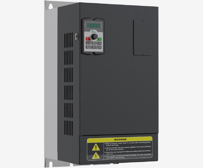
اینورتر 55 کیلووات سه فاز سری سولار پمپ
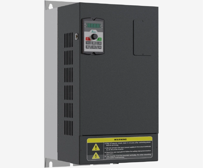
اینورتر 45 کیلووات سه فاز سری سولار پمپ
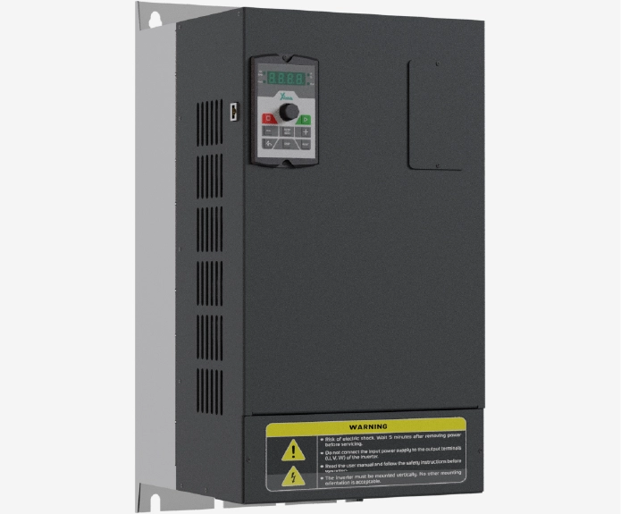
اینورتر 37 کیلووات سه فاز سری سولار پمپ
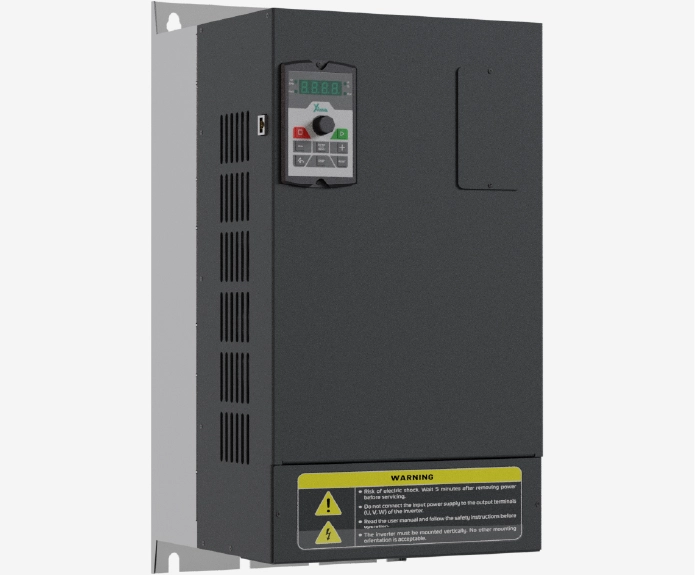
اینورتر 55 کیلووات سه فاز سری صنعتی
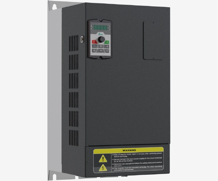
اینورتر 45 کیلووات سه فاز سری صنعتی
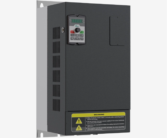
اینورتر 37 کیلووات سه فاز سری صنعتی
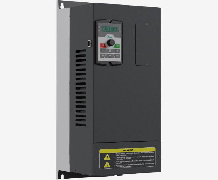
اینورتر 30 کیلووات سه فاز سری سولار پمپ
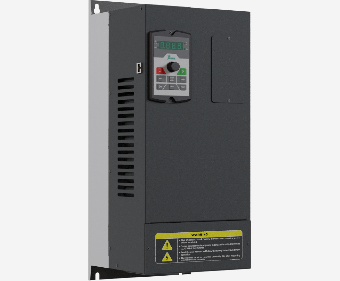
اینورتر 22 کیلووات سه فاز سری سولار پمپ
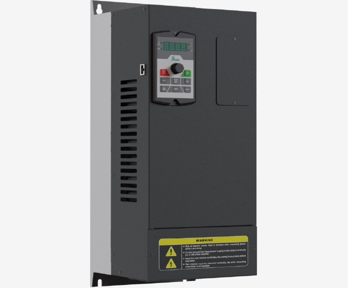
اینورتر 18.5 کیلووات سه فاز سری سولار پمپ
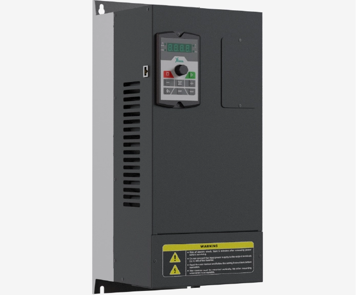
اینورتر 30 کیلووات سه فاز سری صنعتی
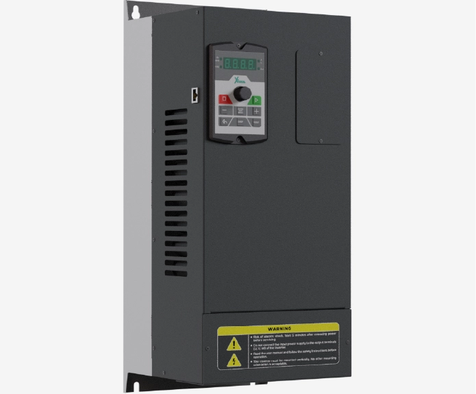
اینورتر 22 کیلووات سه فاز سری صنعتی
نظرات کاربران
دیدگاهها
هنوز دیدگاهی ثبت نشده است.