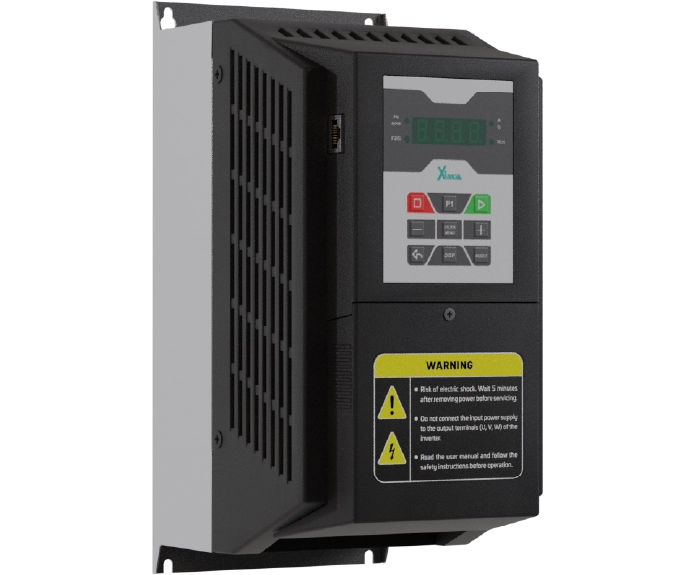
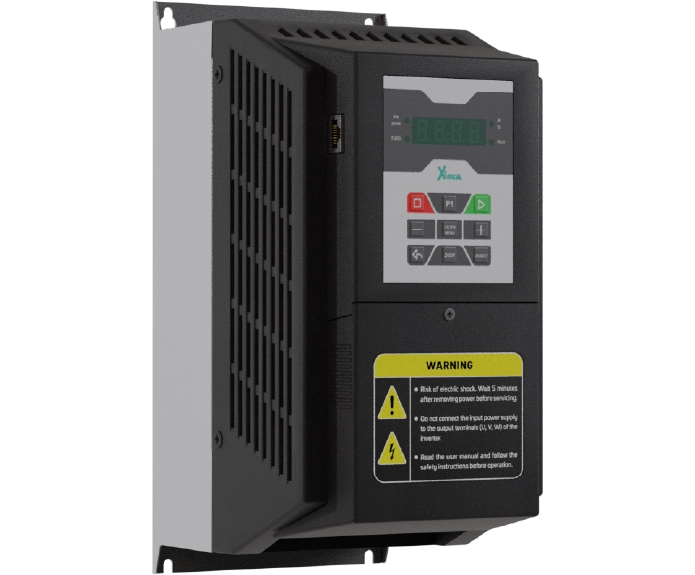
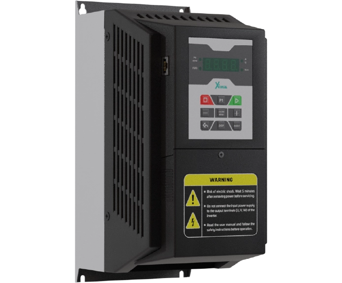
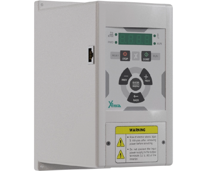
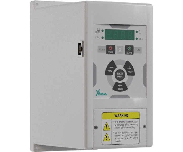
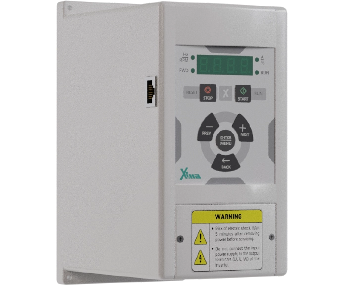
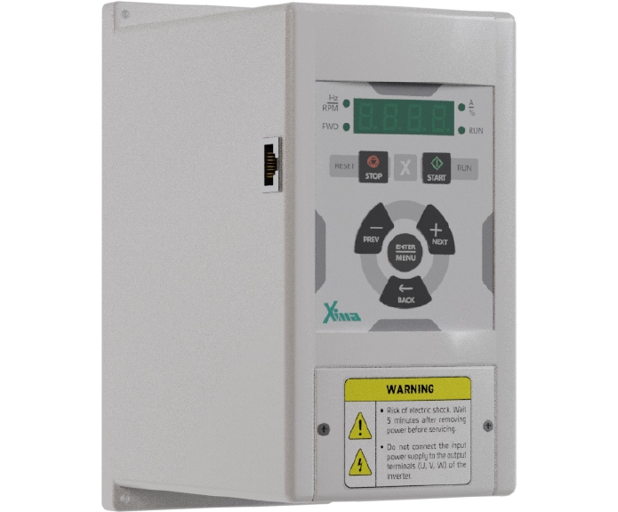
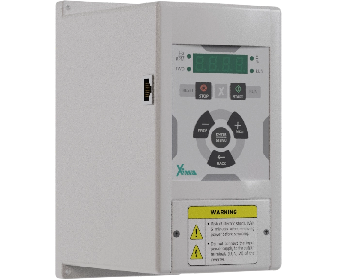
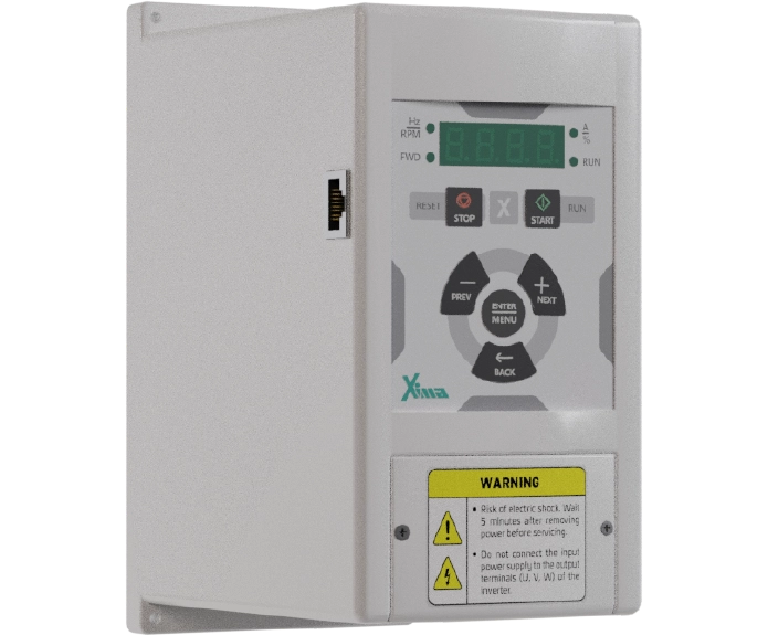
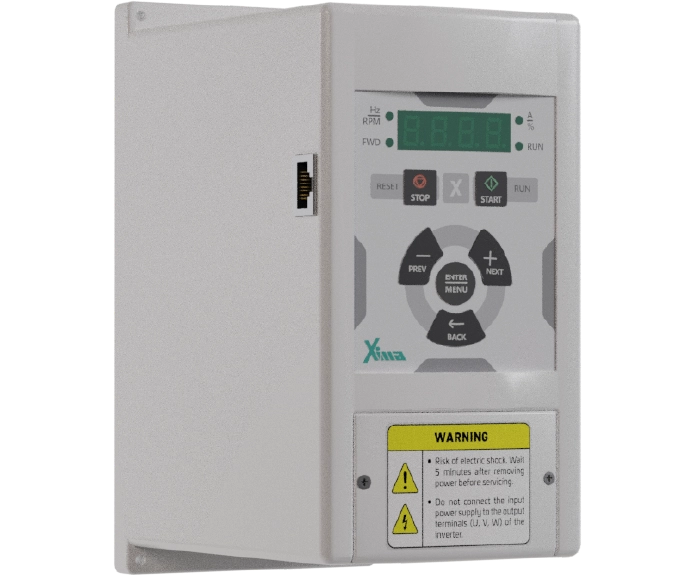
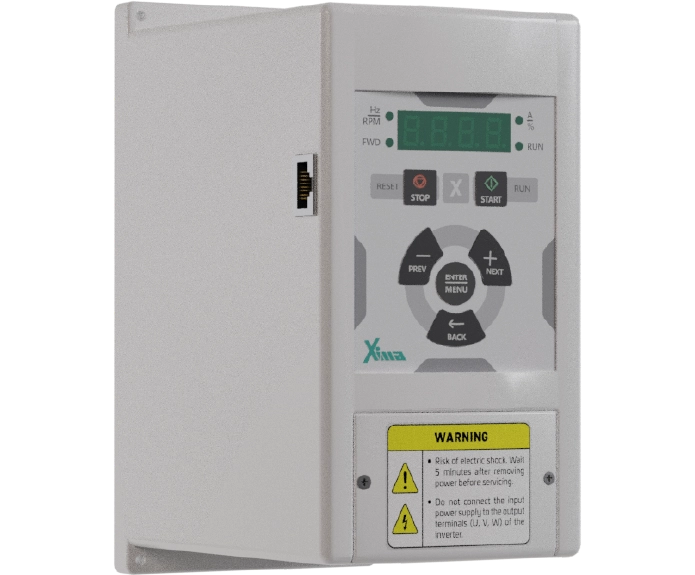
درایو آسانسور و بالابر زیما سری L؛ کنترل تخصصی حرکت الکتروموتور
درایو آسانسور زیما سری L خانوادهای از درایوهای کنترل دور الکتروموتور است که برای مدیریت حرکت در آسانسورهای کششی، بالابرها و تجهیزات بالابری طراحی شده است. این درایوها با تنظیم سرعت و گشتاور موتور، کنترل مراحل شتابگیری، حرکت و توقف را بر عهده دارند و از توابع تخصصی موردنیاز برای هماهنگی با تابلو فرمان و سیستم ترمز استفاده میکنند.
درایوهای آسانسوری زیما با پشتیبانی از روشهای کنترل حلقهباز (Open Loop) و در مدلهای سازگار، حلقهبسته (Closed Loop)، برای کاربردهای متناسب با موتورهای آسنکرون گیربکسی و موتورهای سنکرون گیرلس قابل استفاده هستند.
خانواده سری L زیما در ۱۷ مدل با محدوده توان ۱.۵ تا ۵۵ کیلووات معرفی شده است. تفاوت مشخصات الکتریکی و امکانات کنترلی مدلها، امکان بررسی درایو متناسب با نوع الکتروموتور، ظرفیت سیستم و الزامات حرکتی آسانسور یا بالابر را فراهم میکند.
درایو آسانسور چیست و چه نقشی در کنترل حرکت دارد؟
در سیستمهای آسانسوری، الکتروموتور وظیفه ایجاد نیروی محرکه موردنیاز برای جابهجایی کابین را بر عهده دارد؛ اما حرکت کنترلشده کابین تنها با روشن و خاموش کردن موتور امکانپذیر نیست.
شتابگیری هنگام شروع حرکت، کنترل سرعت در مسیر، کاهش سرعت پیش از رسیدن به طبقه و توقف نهایی، همگی به مدیریت دقیق عملکرد الکتروموتور وابستهاند.
درایو آسانسور یا اینورتر آسانسور با تغییر فرکانس و ولتاژ خروجی، سرعت و گشتاور موتور را مطابق فرمانهای سیستم کنترل تنظیم میکند.
در یک آسانسور کششی، ارتباط اجزای اصلی سیستم به این صورت است:
تابلو فرمان آسانسور ← درایو زیما ← الکتروموتور ← فلکه کشش و مجموعه مکانیکی آسانسور
در این ساختار، تابلو فرمان مسئول مدیریت منطق حرکت، درخواست طبقات و هماهنگی تجهیزات است. درایو نیز مطابق فرمانهای دریافتی، خروجی الکتریکی موتور را کنترل میکند.
درایو آسانسوری زیما علاوه بر کنترل موتور، دارای توابع مرتبط با ترتیب عملکرد ترمز مکانیکی، تنظیم پروفیل حرکت و ارتباط با ورودیها و خروجیهای کنترلی است.
بااینحال، درایو جایگزین تابلو فرمان، مدار ایمنی، گاورنر، ترمز مکانیکی یا سایر تجهیزات حفاظتی الزامی آسانسور نیست.
ویژگیهای فنی درایو آسانسور زیما سری L
کنترل سرعت و گشتاور در مراحل مختلف حرکت
در سیستمهای آسانسوری، شرایط عملکرد موتور هنگام شروع حرکت، سرعت نامی و توقف یکسان نیست.
در لحظه راهاندازی، موتور باید گشتاور مناسب برای کنترل مجموعه مکانیکی را تأمین کند. هنگام حرکت نیز سرعت و گشتاور باید با فرمانهای تابلو و شرایط بار هماهنگ باشند.
درایو زیما امکان تنظیم پارامترهای مربوط به سرعت، شتابگیری، کاهش سرعت و توقف را فراهم میکند.
در مستندات این خانواده، پارامترهایی برای سرعت نامی، سرعت پیادهروی، شتاب اولیه، شتاب توقف و تغییرات شتاب یا Jerk در نظر گرفته شدهاند.
این تنظیمات در شکلدهی پروفیل حرکت نقش دارند و باید بر اساس ویژگیهای موتور، ظرفیت آسانسور و شرایط مکانیکی سیستم انتخاب شوند.
تنظیم صحیح پروفیل حرکت میتواند به کاهش تغییرات ناگهانی شتاب و کنترل بهتر حرکت کابین کمک کند؛ بااینحال کیفیت نهایی حرکت به عملکرد مجموعه مکانیکی، انکودر، تابلو فرمان و تنظیمات درایو نیز وابسته است.
کنترل حلقهباز و حلقهبسته موتور
یکی از تفاوتهای اصلی درایوهای آسانسوری، روش کنترل الکتروموتور است.
در روش کنترل حلقهباز (Open Loop)، درایو بدون دریافت بازخورد مستقیم سرعت از انکودر، عملکرد موتور را بر اساس روش کنترلی و پارامترهای تنظیمشده مدیریت میکند.
این روش در کاربردهای سازگار با موتورهای القایی یا آسنکرون قابل استفاده است.
در مقابل، در روش کنترل حلقهبسته (Closed Loop)، اطلاعات بازخورد انکودر به کنترل دقیقتر وضعیت موتور کمک میکند.
در مدلهای مجهز به کنترل حلقهبسته زیما، امکان استفاده از بازخورد انکودر برای کنترل موتورهای آسنکرون و در پیکربندیهای مخصوص، موتورهای سنکرون گیرلس پیشبینی شده است.
انتخاب روش کنترل به نوع الکتروموتور، مشخصات انکودر و قابلیتهای مدل درایو بستگی دارد و نباید همه مدلهای سری L را دارای امکانات یکسان حلقهبسته در نظر گرفت.
تنظیم خودکار مشخصات موتور (Auto Learning)
برای عملکرد صحیح درایو، مشخصات الکتریکی و کنترلی موتور باید با پارامترهای دستگاه هماهنگ شوند.
زیما از قابلیت Auto Learning یا شناسایی خودکار پارامترهای موتور در پیکربندیهای مرتبط پشتیبانی میکند.
این قابلیت با هدف شناسایی اطلاعات موردنیاز برای تنظیم کنترل موتور به کار میرود و میتواند فرایند پیکربندی درایو را ساختارمندتر کند.
در مدلهای مجهز به کنترل موتور گیرلس، تنظیمات تکمیلی مرتبط با انکودر و موقعیت روتور نیز مطرح میشوند.
اجرای شناسایی خودکار باید مطابق دستورالعمل مدل دستگاه و با رعایت شرایط ایمنی مکانیکی و الکتریکی آسانسور انجام شود.
هماهنگی عملکرد ترمز مکانیکی (Brake Sequence)
در آسانسورهای کششی، زمان آزاد شدن و اعمال مجدد ترمز مکانیکی باید با وضعیت تولید گشتاور و فرمانهای حرکت هماهنگ باشد.
درایوهای آسانسوری زیما دارای توابع مربوط به توالی عملکرد ترمز (Brake Sequence) هستند.
این توابع امکان تنظیم تأخیرهای مرتبط با شروع حرکت، تولید خروجی درایو، آزاد شدن ترمز و توقف موتور را فراهم میکنند.
هماهنگی صحیح میان درایو، تابلو فرمان و ترمز مکانیکی برای کنترل حرکت هنگام شروع و پایان سفر اهمیت دارد.
تنظیم نامناسب این بخش ممکن است باعث تکان اولیه، حرکت ناخواسته یا توقف نامطلوب شود. به همین دلیل، سیمبندی و پارامترهای ترمز باید با توجه به طراحی واقعی مدار فرمان و الزامات ایمنی بررسی شوند.
کنترل موقعیت و کاهش عقبگرد کابین
در آسانسورهای کششی، بهویژه سیستمهای گیرلس، اختلاف گشتاور بار و وضعیت کنترل موتور هنگام آزاد شدن ترمز میتواند باعث حرکت کوتاهمدت ناخواسته کابین شود.
در مستندات زیما، تنظیماتی برای کنترل وضعیت موتور در لحظه شروع حرکت و مدیریت پدیده عقبگرد یا Back Roll در پیکربندیهای گیرلس پیشبینی شده است.
این توابع با استفاده از کنترل موتور و بازخورد مناسب، به مدیریت موقعیت موتور در مرحله گذار میان توقف و حرکت کمک میکنند.
عملکرد صحیح آنها وابسته به انتخاب مدل دارای قابلیت مربوطه، تنظیم انکودر، شناسایی موتور و هماهنگی ترمز مکانیکی است.
کنترل توقف و همسطح شدن کابین با طبقه
یکی از مراحل مهم حرکت آسانسور، کاهش سرعت و توقف کابین در موقعیت تعیینشده است.
درایو زیما با استفاده از پارامترهای سرعت، شتاب و توابع توقف، امکان تنظیم رفتار موتور در مرحله نزدیک شدن به طبقه را فراهم میکند.
در مستندات خانواده L، روشهایی مانند Distance Approach و در پیکربندیهای خاص گیرلس، Direct Approach معرفی شدهاند.
قابلیت Direct Approach به همه مدلهای زیما تعلق ندارد و باید پیش از استفاده، پشتیبانی آن در مدل و روش کنترل انتخابشده بررسی شود.
دقت توقف نهایی تنها به عملکرد درایو وابسته نیست؛ موقعیت سنسورها، فرمانهای تابلو آسانسور، ویژگیهای مجموعه مکانیکی و تنظیمات انکودر نیز در آن نقش دارند.
پشتیبانی از مد نجات اضطراری (Rescue Mode)
هنگام قطع برق، عملکرد سیستم آسانسور باید مطابق طراحی مدار نجات و الزامات ایمنی مدیریت شود.
در مستندات درایو آسانسور زیما، توابع مربوط به مد نجات اضطراری (Rescue Mode) پیشبینی شدهاند.
این توابع در پیکربندیهای سازگار، امکان استفاده از منبع تغذیه اضطراری مناسب مانند UPS و اجرای حرکت کنترلشده در شرایط نجات را فراهم میکنند.
پارامترهایی برای روش عملکرد در حالت نجات، توان قابلاستفاده منبع اضطراری، سرعت حرکت و شرایط فعالسازی ورودیهای کنترلی وجود دارند.
اجرای مد نجات به وجود تجهیزات تغذیه اضطراری، مدار فرمان مناسب و هماهنگی کامل با سیستم ایمنی آسانسور وابسته است.
بنابراین وجود این قابلیت در درایو بهتنهایی به معنی مجهز بودن آسانسور به سیستم نجات کامل و آماده بهرهبرداری نیست.
معرفی مدلهای درایو آسانسور و بالابر زیما
درایوهای سری L زیما در محدوده توان ۱.۵ تا ۵۵ کیلووات و در چند اندازه بدنه یا فریم ارائه شدهاند.
بر اساس فهرست مدلهای منتشرشده در فلایر رسمی این خانواده، مجموعه شامل ۱۷ مدل در کلاسهای ورودی AC تکفاز ۲۲۰ ولت و سهفاز ۳۸۰ ولت است.
مدلها از نظر توان و اندازه فریم در گروههای زیر قرار میگیرند:
- مدلهای تکفاز ۲۲۰ ولت: شامل سه توان ۱.۵، ۲.۲ و ۳ کیلووات در فریم B هستند. این مدلها دارای ورودی AC تکفاز ۲۲۰ ولت و خروجی سهفاز ۲۲۰ ولتاند.
- مدلهای سهفاز فریم B: شامل توانهای ۱.۵، ۲.۲، ۳، ۴ و ۵.۵ کیلووات هستند و در کلاس ورودی و خروجی سهفاز ۳۸۰ ولت قرار میگیرند.
- مدلهای فریم C: توانهای ۷.۵، ۱۱ و ۱۵ کیلووات را پوشش میدهند و برای بررسی در سامانههایی با موتور سهفاز متناسب با جریان و ظرفیت دستگاه ارائه شدهاند.
- مدلهای فریم D: شامل توانهای ۱۸.۵، ۲۲ و ۳۰ کیلووات هستند و در کلاس سهفاز ۳۸۰ ولت قرار دارند.
- مدلهای فریم E: محدوده توان ۳۷، ۴۵ و ۵۵ کیلووات را پوشش میدهند و بالاترین گروه توانی معرفیشده در فلایر سری L به شمار میروند.
این دستهبندی بر اساس توان و مشخصات بدنه محصولات است. امکانات کنترلی مدلها، بهویژه پشتیبانی از موتور گیرلس، انکودر و روشهای خاص توقف، باید جداگانه بررسی شوند.
برای انتخاب درایو مناسب، علاوه بر توان موتور، جریان نامی، ولتاژ، نوع موتور، روش کنترل و الزامات حرکتی سیستم اهمیت دارند.
اطلاعات مدلها، جریانهای نامی و ابعاد دستگاهها در فلایر فنی درایوهای آسانسور و بالابر درج شده است.
تفاوت درایو زیما برای آسانسور گیربکس و گیرلس
درایو آسانسور گیربکس
در آسانسورهای گیربکسی، موتور الکتریکی از طریق یک مجموعه گیربکس به فلکه کشش متصل میشود.
در این ساختار، الکتروموتور معمولاً از نوع القایی یا آسنکرون است و درایو وظیفه کنترل سرعت و گشتاور آن را مطابق شرایط حرکت بر عهده دارد.
درایو زیما در مدلها و پیکربندیهای سازگار میتواند برای کنترل موتورهای گیربکسی به روش حلقهباز یا حلقهبسته مورد استفاده قرار گیرد.
انتخاب روش کنترل به مشخصات موتور، وجود تجهیزات بازخورد و نیازهای حرکتی سیستم وابسته است.
درایو آسانسور گیرلس
در آسانسورهای گیرلس، فلکه کشش بدون استفاده از گیربکس واسط به مجموعه موتور متصل است. بسیاری از این سیستمها از موتورهای سنکرون مغناطیس دائم (PMSM) استفاده میکنند.
در این کاربرد، کنترل وضعیت روتور و بازخورد انکودر نقش مهمی در تولید گشتاور و کنترل حرکت دارند.
مدلهای زیما که برای کنترل حلقهبسته موتور سنکرون طراحی شدهاند، دارای تنظیمات مرتبط با پارامترهای موتور، جهت و آفست انکودر و کنترل وضعیت حرکت هستند.
قابلیتهای خاص کنترل گیرلس را نباید به همه مدلهای سری L تعمیم داد؛ زیرا پشتیبانی آنها به سختافزار، نرمافزار و نوع روش کنترل دستگاه بستگی دارد.
کاربردهای درایو زیما در آسانسور و تجهیزات بالابری
آسانسورهای کششی مسافربر
در آسانسورهای کششی مسافربر، کنترل مراحل شروع حرکت، شتابگیری، حرکت با سرعت نامی و توقف در طبقه از وظایف اصلی سیستم محرکه است.
درایو آسانسور زیما با دریافت فرمانهای مناسب از تابلو، خروجی موتور را مطابق پروفیل تنظیمشده کنترل میکند.
نوع موتور، ظرفیت کابین، سرعت نامی و طراحی مکانیکی سیستم در تعیین مشخصات درایو نقش دارند.
آسانسورهای کششی باری
در آسانسورهای باری، تغییرات بار و شرایط راهاندازی میتوانند بر گشتاور موردنیاز موتور اثر بگذارند.
برای این کاربردها، انتخاب درایو باید با بررسی جریان نامی موتور، ظرفیت اضافهبار، وضعیت بارگذاری و شرایط مکانیکی مجموعه انجام شود.
یکسان بودن توان نامی دو موتور به معنی یکسان بودن شرایط راهاندازی و الزامات کنترل آنها نیست.
بالابرهای صنعتی
در سیستمهای بالابر صنعتی، اینورتر بالابر میتواند برای تنظیم سرعت و گشتاور موتور و هماهنگی حرکت با تجهیزات فرمان و ترمز استفاده شود.
در این کاربردها، نوع بار، تعداد دفعات راهاندازی، جهت حرکت و شرایط توقف اهمیت دارند.
بهویژه در بالابرهای دارای بار معلق، انتخاب تجهیزات و روش کنترل باید با الزامات ایمنی و مکانیکی سیستم هماهنگ باشد.
جرثقیلها و تجهیزات جابهجایی بار
درایوهای تخصصی بالابری زیما برای بررسی در بخشهای مناسب از تجهیزات جرثقیل و جابهجایی بار نیز معرفی شدهاند.
کنترل حرکت در این تجهیزات به ویژگیهای موتور، عملکرد ترمز، ماهیت بار و شرایط کاری وابسته است.
قابلیت استفاده از یک مدل درایو برای جرثقیل باید بر اساس مشخصات فنی همان دستگاه و الزامات سیستم بالابری ارزیابی شود؛ زیرا نیازهای کنترلی و حفاظتی همه تجهیزات جابهجایی بار یکسان نیست.
تفاوت درایو آسانسور زیما با اینورتر صنعتی عمومی
اینورتر صنعتی عمومی برای کنترل سرعت و گشتاور الکتروموتور در کاربردهایی مانند نوار نقاله، فن، ماشینآلات و تجهیزات تولیدی استفاده میشود.
در مقابل، درایو آسانسور علاوه بر کنترل موتور، باید با توالی عملکرد ترمز، فرمانهای حرکت، پروفیل سرعت و نیازهای ویژه توقف در سیستم آسانسوری هماهنگ باشد.
درایوهای سری L زیما دارای توابعی هستند که برای این نوع کاربردها در نظر گرفته شدهاند؛ از جمله:
- تنظیم سرعت و شتاب متناسب با مراحل حرکت آسانسور
- توالی فرمانهای مرتبط با ترمز مکانیکی
- ورودیها و خروجیهای کنترلی مخصوص ارتباط با تابلو فرمان
- تنظیمات حالت رویزیون یا Inspection
- مد نجات اضطراری در پیکربندیهای سازگار
- کنترل حلقهبسته و انکودر در مدلهای مجهز
- توابع مرتبط با توقف و نزدیک شدن به طبقه
وجود این قابلیتها، درایو آسانسوری را از نظر نرمافزار کاربردی و الزامات راهاندازی از بسیاری از اینورترهای صنعتی متعارف متمایز میکند.
بااینحال، استفاده صحیح از آن همچنان به طراحی مناسب تابلو، انتخاب تجهیزات ایمنی و تنظیمات تخصصی نیاز دارد.
معیارهای مهندسی انتخاب درایو آسانسور زیما
مشخصات الکتریکی الکتروموتور
توان، جریان نامی، ولتاژ، فرکانس و سرعت نامی موتور از اطلاعات اصلی برای انتخاب درایو هستند.
جریان خروجی نامی درایو باید با شرایط الکتریکی موتور و نیاز گشتاور سیستم هماهنگ باشد.
در آسانسور، بررسی ظرفیت اضافهبار و جریان موردنیاز هنگام راهاندازی و شتابگیری نیز اهمیت دارد.
انتخاب مدل فقط بر اساس توان درجشده روی پلاک موتور، بدون بررسی سایر شرایط، کافی نیست.
نوع موتور: گیربکس یا گیرلس
ساختار موتور تعیین میکند چه روش کنترلی موردنیاز است.
در سیستمهای دارای موتور آسنکرون میتوان متناسب با امکانات مدل، روش کنترل حلقهباز یا حلقهبسته را بررسی کرد.
در سیستمهای دارای موتور سنکرون گیرلس، پشتیبانی از روش کنترل مخصوص موتور و تجهیزات بازخورد مناسب باید تأیید شود.
ظرفیت کابین و مشخصات مکانیکی
ظرفیت نامی آسانسور، سرعت حرکت، نسبت تعلیق، وزن کابین، وزنه تعادل و مشخصات سیستم کشش بر شرایط بارگذاری موتور اثر میگذارند.
برای ارزیابی ظرفیت مناسب درایو، اطلاعات واقعی مجموعه مکانیکی و ویژگیهای بار باید در کنار مشخصات موتور بررسی شوند.
انکودر و سیستم بازخورد
در کاربردهای حلقهبسته، نوع انکودر، تعداد پالس، نحوه اتصال، سازگاری کارت بازخورد و تنظیم جهت و موقعیت انکودر اهمیت دارند.
این اطلاعات بهویژه در سیستمهای گیرلس و کنترلهای نیازمند بازخورد دقیق موتور ضروری هستند.
تابلو فرمان و ورودیهای کنترلی
تعداد و نوع ورودیهای دیجیتال، فرمانهای جهت حرکت، سرعتهای تعریفشده، سیگنال Enable و خروجیهای مرتبط با ترمز باید با مشخصات تابلو آسانسور سازگار باشند.
هماهنگی درایو و تابلو فرمان، بخشی از طراحی سیستم کنترل حرکت است و باید پیش از راهاندازی نهایی ارزیابی شود.
ترمز مکانیکی و شرایط برگشت انرژی
در آسانسورهای کششی، بسته به جهت حرکت و وضعیت بار، موتور ممکن است در بخشی از سفر در شرایط تولید انرژی برگشتی قرار گیرد.
در این حالت، عملکرد مدار ترمز و تجهیزات مرتبط با مدیریت انرژی برگشتی اهمیت دارد.
زیما امکان استفاده از مقاومت ترمز را در مشخصات فنی این خانواده معرفی کرده است.
مقدار مقاومت، توان قابلتحمل و شرایط نصب باید بر اساس مدل درایو، انرژی برگشتی و دستورالعمل سازنده تعیین شوند.
الزامات نصب و راهاندازی درایو آسانسور زیما
نصب و راهاندازی درایو آسانسوری باید توسط افراد متخصص و با توجه به مدار فرمان، مشخصات الکتروموتور و الزامات ایمنی انجام شود.
درایو بخشی از سیستم الکترونیک قدرت آسانسور است و سیمبندی نامناسب یا تنظیم اشتباه پارامترهای کنترلی میتواند بر عملکرد مجموعه اثر بگذارد.
در مرحله نصب، باید شرایط تهویه تابلو، اتصال زمین، حفاظت ورودی، سیمبندی موتور، کابلهای فرمان و تجهیزات بازخورد بررسی شوند.
در سیستمهای دارای انکودر، رعایت اصول کابلکشی و کاهش تداخل الکترومغناطیسی اهمیت ویژهای دارد.
پس از نصب الکتریکی، پارامترهای موتور، پروفیل سرعت، ترمز، ورودیها و خروجیهای فرمان و حالتهای حرکتی باید متناسب با شرایط سیستم تنظیم شوند.
همچنین عملکرد سیستم در حالتهای عادی، رویزیون و نجات اضطراری ــ در صورت تجهیز و پشتیبانی ــ باید طبق دستورالعمل مربوطه ارزیابی شود.
درجه حفاظت IP20 که در مشخصات رسمی فریمهای مستندشده زیما درج شده است، به معنی مناسب بودن دستگاه برای نصب مستقیم در محیطهای مرطوب یا پرگردوغبار نیست. تابلو یا محفظه نصب باید متناسب با شرایط محیطی انتخاب شود.
مستندات فنی و راهنمای تنظیم درایو زیما
برای بررسی مشخصات مدلها، نقشه اتصالات، تنظیمات موتور و توابع کنترلی، استفاده از مستندات رسمی زیما ضروری است.
دفترچه راهنمای نصب و راهاندازی درایو زیما سری L شامل بخشهای مرتبط با موارد زیر است:
- نصب مکانیکی و الکتریکی دستگاه
- ترمینالهای قدرت و فرمان
- اتصالات انکودر و کارت PG
- تنظیم مشخصات موتور و Auto Learning
- کنترل حلقهباز و حلقهبسته
- تنظیم سرعت، شتاب و توالی ترمز
- پارامترهای مد نجات اضطراری
- توابع حفاظتی، کدهای خطا و راهنمای بررسی خطاها
قبل از استفاده از جدولهای پارامتر یا دستورالعملهای سیمبندی، باید اطمینان حاصل شود که نسخه دفترچه با مدل، سختافزار و نسخه نرمافزار دستگاه مطابقت دارد.
پرسشهای متداول درباره درایو آسانسور زیما
درایو آسانسور زیما چه وظیفهای دارد؟
درایو زیما وظیفه تنظیم خروجی الکتریکی موتور را برای کنترل سرعت و گشتاور بر عهده دارد. این کنترل مطابق فرمانهای تابلو آسانسور انجام میشود و در مراحل راهاندازی، حرکت و توقف نقش دارد.
آیا درایو زیما برای آسانسورهای گیربکسی مناسب است؟
بله، مدلهای سازگار این خانواده برای کنترل موتورهای آسنکرون مورد استفاده در آسانسورهای گیربکسی طراحی شدهاند. انتخاب نهایی به مشخصات موتور، توان و جریان موردنیاز و روش کنترل بستگی دارد.
آیا درایو آسانسور زیما از موتور گیرلس پشتیبانی میکند؟
مدلهای مجهز به کنترل حلقهبسته مخصوص موتور سنکرون، قابلیت استفاده در سیستمهای گیرلس سازگار را دارند. این ویژگی به همه مدلهای سری L تعلق ندارد و باید مشخصات مدل و سیستم انکودر بررسی شود.
تفاوت کنترل حلقهباز و حلقهبسته در آسانسور چیست؟
در کنترل حلقهباز، درایو بدون دریافت بازخورد مستقیم انکودر، موتور را بر اساس روش کنترلی و پارامترهای تنظیمشده مدیریت میکند.
در کنترل حلقهبسته، اطلاعات بازخورد موتور در حلقه کنترل استفاده میشود و امکان مدیریت دقیقتر شرایط حرکتی در کاربردهای سازگار را فراهم میکند.
آیا زیما قابلیت کنترل ترمز مکانیکی آسانسور را دارد؟
بله. درایوهای آسانسوری زیما دارای توابع مرتبط با توالی عملکرد ترمز هستند. استفاده صحیح از این قابلیت به سیمبندی، تنظیم پارامترها و هماهنگی با تابلو فرمان و تجهیزات مکانیکی وابسته است.
آیا درایو زیما مد نجات اضطراری دارد؟
در مستندات سری L، عملکرد مد نجات اضطراری و روشهای استفاده از منبع تغذیه سازگار توضیح داده شده است. اجرای این قابلیت مستلزم وجود تجهیزات و مدارهای مناسب و رعایت الزامات ایمنی آسانسور است.
آیا میتوان از برق تکفاز برای راهاندازی موتور سهفاز با درایو زیما استفاده کرد؟
در مدلهای مشخصی که دارای ورودی AC تکفاز ۲۲۰ ولت و خروجی سهفاز ۲۲۰ ولت هستند، این امکان برای موتور سازگار وجود دارد.
در این شرایط، ولتاژ نامی موتور، جریان، نوع اتصال سیمپیچ و نیاز گشتاور سیستم باید بررسی شوند.
آیا از درایو آسانسور زیما میتوان برای بالابر یا جرثقیل استفاده کرد؟
درایوهای این خانواده برای کاربردهای آسانسوری و بالابری معرفی شدهاند. بااینحال سازگاری هر مدل با بالابر یا جرثقیل مشخص، باید بر اساس الزامات کنترل موتور، نوع بار، تجهیزات ترمز و شرایط ایمنی همان سیستم تأیید شود.
جمعبندی
درایو آسانسور و بالابر زیما سری L برای مدیریت سرعت، گشتاور و مراحل حرکت الکتروموتور در سیستمهای کششی و تجهیزات بالابری طراحی شده است.
توابع تخصصی مربوط به پروفیل سرعت، هماهنگی ترمز، شناسایی پارامترهای موتور و در مدلهای مجهز، کنترل حلقهبسته و بازخورد انکودر، از ویژگیهای فنی این خانواده به شمار میروند.
تنوع مدلهای معرفیشده از ۱.۵ تا ۵۵ کیلووات، امکان بررسی درایو برای ظرفیتها و نیازهای متفاوت را فراهم میکند؛ بااینحال انتخاب صحیح باید بر اساس مشخصات موتور، ساختار مکانیکی آسانسور، نوع روش کنترل، تجهیزات جانبی و الزامات ایمنی انجام شود.
برای بررسی انطباق مشخصات درایو زیما با نوع موتور، تابلو فرمان و شرایط فنی پروژه میتوان از طریق ارتباط با کارشناسان فنی زیما اطلاعات مجموعه را ارائه کرد.
XIMA L-Series Elevator and Lift Drives | Specialized Motor Control
The XIMA L-Series Elevator and Lift Drives are application-specific variable frequency drives (VFDs) designed to control electric motors in traction elevators, industrial lifts, cranes, and related lifting equipment. By regulating motor speed and torque, these drives manage acceleration, travel, deceleration, and stopping while providing dedicated functions for coordination with elevator controllers and mechanical braking systems.
XIMA elevator drives support open-loop motor control and, in compatible configurations, closed-loop control with encoder feedback. Depending on the model and control configuration, they can be used with geared induction motors and gearless permanent magnet synchronous motors (PMSMs).
The official XIMA L-Series technical brochure covers 17 drive variants from 1.5 kW to 55 kW, while the current online product category lists 11 models from 1.5 kW to 15 kW. Differences in power ratings, electrical specifications, and control capabilities allow a suitable drive to be evaluated according to motor type, elevator capacity, and motion control requirements.
What Is an Elevator Drive and How Does It Control Motion?
In an elevator system, the electric motor generates the mechanical power required to move the elevator car. However, controlled elevator movement requires considerably more than switching the motor on and off.
Acceleration during departure, speed regulation throughout travel, deceleration when approaching a floor, and final stopping all depend on coordinated motor control.
An elevator drive, also referred to as an elevator VFD or elevator inverter, regulates motor output voltage and frequency to control speed and torque according to commands from the elevator control system.
In a typical traction elevator, the main control arrangement can be represented as:
Elevator Controller → XIMA Drive → Electric Motor → Traction Sheave and Elevator Mechanical System
The elevator controller manages operating logic, floor requests, travel commands, and coordination with other equipment. The drive controls the motor’s electrical output in response to the commands received.
XIMA elevator drives also incorporate functions related to mechanical brake sequencing, travel profile configuration, and communication with external control inputs and outputs.
However, an elevator drive does not replace the elevator controller, safety circuit, overspeed governor, mechanical brake, or other mandatory safety components.
Technical Features of XIMA L-Series Elevator Drives
Motor Speed and Torque Control Throughout Elevator Travel
The operating requirements of an elevator motor change throughout the travel cycle.
At startup, the motor must develop sufficient torque to control the mechanical load. During normal travel, speed and torque must remain coordinated with the elevator controller and the current loading conditions.
XIMA drives provide configurable parameters for motor speed, acceleration, deceleration, and stopping.
The technical documentation includes settings for rated travel speed, leveling speed, initial acceleration, stopping deceleration, and jerk, which describes the rate of change of acceleration.
These parameters are used to establish the elevator’s motion profile and must be configured according to the motor characteristics, elevator capacity, and mechanical properties of the installation.
Proper motion profile configuration can help reduce abrupt acceleration changes and improve the control of car movement.
Nevertheless, overall ride quality also depends on the mechanical system, encoder performance, elevator controller, and drive configuration.
Open-Loop and Closed-Loop Motor Control
One of the main differences between elevator drive configurations is the method used to control the electric motor.
In open-loop control, the drive operates the motor without direct encoder feedback, using its control algorithm and configured motor parameters to regulate operation.
This method can be used in compatible applications involving asynchronous induction motors.
In closed-loop control, encoder feedback provides information that allows the drive to regulate motor operation with greater precision.
XIMA drive models equipped with closed-loop control can use encoder feedback for asynchronous motors and, in dedicated configurations, permanent magnet synchronous motors used in gearless elevators.
The appropriate control method depends on the motor type, encoder specifications, and capabilities of the selected drive.
Not every L-Series model should be assumed to provide the same closed-loop control functions.
Automatic Motor Parameter Identification (Auto Learning)
Accurate motor control requires the drive parameters to be matched to the electrical and operating characteristics of the connected motor.
XIMA supports Auto Learning, also known as motor parameter identification, in applicable configurations.
This function identifies information needed by the motor control algorithm and supports a more structured drive commissioning process.
For models designed to control gearless synchronous motors, additional configuration may involve encoder settings and rotor position information.
Automatic motor identification must be performed according to the instructions for the selected drive model, with appropriate electrical and mechanical safety precautions.
Mechanical Brake Sequencing
In traction elevators, the timing of mechanical brake release and engagement must be coordinated with motor torque production and travel commands.
XIMA elevator drives incorporate functions related to Brake Sequencing.
These functions allow relevant delays and operating conditions to be configured for motor startup, drive output activation, brake release, and motor stopping.
Correct coordination between the drive, elevator controller, and mechanical brake is important for controlling movement during departure and arrival.
Incorrect brake timing or configuration can result in startup jerks, unintended movement, or unsatisfactory stopping behaviour.
For this reason, brake wiring and control parameters must be evaluated against the actual elevator control circuit and applicable safety requirements.
Position Control and Elevator Rollback Reduction
In traction elevator systems, particularly gearless installations, differences in load torque and motor control conditions during brake release may cause a short period of unintended car movement.
This phenomenon is commonly known as elevator rollback or back roll.
XIMA technical documentation describes functions associated with managing motor behaviour during the transition from standstill to motion in compatible gearless configurations.
Through appropriate motor control and encoder feedback, these functions help manage motor position and torque during the initial movement phase.
Their effectiveness depends on the capabilities of the selected drive, encoder configuration, motor identification, and mechanical brake coordination.
Floor Approach and Elevator Leveling Control
A critical part of elevator travel is the transition from normal running speed to the final stopping position at the destination floor.
XIMA drives provide speed, acceleration, deceleration, and stopping parameters that can be configured to manage motor behaviour during floor approach.
The technical documentation describes methods such as Distance Approach and, for specific gearless closed-loop configurations, Direct Approach.
Direct Approach is not a universal feature across all XIMA elevator drive models. Its availability must be confirmed for the selected model and control method.
Final leveling accuracy also depends on floor sensors, elevator controller commands, mechanical characteristics, and encoder configuration.
Emergency Rescue Mode
During a power failure, elevator operation must be managed according to the installed emergency rescue system and applicable safety requirements.
XIMA elevator drive documentation includes functions associated with Emergency Rescue Mode.
In compatible configurations, these functions can support controlled elevator movement using a suitable emergency power source, such as an appropriately specified UPS.
The available settings cover aspects of rescue operation, emergency power capacity, operating speed, and control input activation.
Implementing rescue operation requires suitable emergency power equipment, control circuits, and complete coordination with the elevator safety system.
The presence of a rescue function in the drive does not, by itself, mean that the elevator has a complete and operational emergency rescue system.
XIMA Elevator and Lift Drive Models
The XIMA L-Series technical brochure presents models with power ratings ranging from 1.5 kW to 55 kW, organised into different enclosure sizes and electrical supply classes.
The published range includes single-phase 220 V AC input configurations and three-phase 380 V AC input configurations.
The model groups can be described according to power rating and enclosure size:
- Single-phase 220 V input models: Available in 1.5, 2.2, and 3 kW ratings with B-size enclosures. These models use a single-phase 220 V AC input and provide a three-phase 220 V motor output.
- Three-phase B-size models: Include 1.5, 2.2, 3, 4, and 5.5 kW ratings. They are designed for the three-phase 380 V input and output voltage class.
- C-size models: Cover 7.5, 11, and 15 kW ratings and are intended for evaluation with compatible three-phase motors according to the rated output current and operating requirements.
- D-size models: Include 18.5, 22, and 30 kW ratings within the three-phase 380 V class.
- E-size models: Cover the higher power ratings of 37, 45, and 55 kW, representing the largest power group documented in the published L-Series brochure.
This grouping describes the electrical power range and enclosure sizes rather than identical control capabilities across all models.
Motor compatibility, encoder support, gearless motor control, and specialized floor approach functions must be evaluated separately for each drive configuration.
Selecting an appropriate XIMA elevator drive requires consideration of rated motor current, voltage, motor type, control method, and the motion control requirements of the installation.
For detailed model information, rated currents, dimensions, and technical characteristics, refer to the XIMA L-Series Technical Overview.
XIMA Elevator Drives for Geared and Gearless Motors
Geared Elevator Motor Control
In a geared traction elevator, the electric motor is connected to the traction sheave through a gearbox.
These systems commonly use asynchronous induction motors, with the drive regulating motor speed and torque according to the elevator’s operating conditions.
Compatible XIMA drive models can be configured for geared motor applications using open-loop or closed-loop control, depending on the available drive functions.
The control method should be selected according to the motor specifications, feedback equipment, and required motion characteristics.
Gearless Elevator Motor Control
In a gearless elevator, the traction sheave is connected directly to the motor assembly without an intermediate reduction gearbox.
Many gearless systems use Permanent Magnet Synchronous Motors (PMSMs).
In these applications, rotor position information and encoder feedback are particularly important for motor torque production and movement control.
XIMA models designed for closed-loop synchronous motor control include settings related to motor parameters, encoder direction, encoder offset, and motion control.
Gearless motor control capabilities must not be attributed to every L-Series model.
Compatibility depends on the drive hardware, firmware, feedback interface, and selected motor control method.
Applications of XIMA Elevator and Lift Drives
Passenger Traction Elevators
In passenger traction elevators, controlling startup, acceleration, rated travel speed, deceleration, and stopping is essential to the drive system’s operation.
The XIMA elevator drive receives the necessary commands from the elevator controller and regulates motor output according to the configured motion profile.
Motor type, car capacity, rated speed, and mechanical design all influence drive selection and configuration.
Freight Elevators
In freight elevators, variations in transported load may significantly affect the torque required during startup and travel.
Drive selection must therefore consider motor rated current, overload capability, loading conditions, and the mechanical characteristics of the system.
Two motors with identical rated power may have different startup and control requirements depending on their applications.
Industrial Lifting Equipment
In industrial lifting systems, a lift inverter may be used to regulate motor speed and torque while coordinating motion with the control and braking equipment.
Load type, starting frequency, direction changes, and stopping conditions are important considerations in these applications.
For equipment carrying suspended loads, the drive and its control method must be integrated with the mechanical design and safety requirements of the lifting system.
Cranes and Load Handling Equipment
XIMA’s lifting drive family is also described for suitable crane and load-handling applications.
Motor control requirements in such equipment depend on the motor type, braking system, load characteristics, and operating conditions.
The suitability of a specific drive model for a crane must be established according to the equipment’s technical requirements and applicable safety standards.
Not all cranes and lifting systems share the same control or protection requirements.
XIMA Elevator Drives vs. General-Purpose Industrial VFDs
General-purpose industrial variable frequency drives are used to control electric motors in applications such as conveyors, fans, machinery, and production equipment.
An elevator drive, by comparison, must also coordinate motor operation with brake sequencing, travel commands, speed profiles, and stopping requirements specific to elevator systems.
XIMA L-Series drives incorporate application-oriented functions, including:
- Configurable travel speeds and acceleration profiles for different movement stages.
- Control functions associated with mechanical brake sequencing.
- Digital inputs and outputs for communication with elevator control equipment.
- Inspection mode configuration.
- Emergency rescue functions in compatible configurations.
- Closed-loop motor control and encoder feedback in equipped models.
- Floor approach and stopping functions.
These features distinguish application-specific elevator drives from many conventional industrial VFDs in terms of operating software and commissioning requirements.
However, correct operation still depends on proper controller integration, suitable safety equipment, and specialized configuration.
Engineering Considerations for Selecting a XIMA Elevator Drive
Electric Motor Specifications
Rated motor power, current, voltage, frequency, and nominal speed are essential inputs for selecting a suitable drive.
The drive’s rated output current must be compatible with the electrical characteristics of the motor and the torque requirements of the elevator system.
Overload capacity and the current required during startup and acceleration must also be considered.
Selecting a drive solely according to the power indicated on the motor nameplate is not sufficient.
Geared or Gearless Motor Configuration
The motor construction determines the control methods that may be required.
For asynchronous induction motors, open-loop or closed-loop operation can be evaluated according to the capabilities of the selected drive.
For gearless synchronous motors, support for the required motor control method and compatible encoder feedback must be confirmed.
Elevator Capacity and Mechanical Characteristics
Rated elevator capacity, travel speed, suspension ratio, car weight, counterweight configuration, and traction system characteristics affect motor loading conditions.
Evaluating the appropriate drive capacity requires information about both the motor and the actual mechanical system.
Encoder and Feedback Requirements
In closed-loop applications, encoder type, signal configuration, pulse resolution, feedback interface compatibility, and encoder direction settings are important.
These considerations are particularly relevant to gearless installations and applications requiring precise motor feedback.
Elevator Controller Compatibility
Digital input and output requirements, direction commands, predefined speeds, enable signals, and brake-related outputs must be compatible with the elevator controller.
Coordination between the drive and the elevator controller is part of the overall motion control design and must be evaluated before commissioning.
Mechanical Braking and Regenerative Energy
In traction elevators, the motor may operate in a regenerative condition during certain parts of the travel cycle, depending on movement direction and the relationship between the car load and counterweight.
In these conditions, the management of regenerated electrical energy and the operation of the braking circuit become important.
XIMA includes provisions for the connection of braking resistors in the documented L-Series configurations.
Resistor value, power rating, and installation requirements must be determined according to the drive model, expected regenerated energy, and manufacturer specifications.
Installation and Commissioning Requirements
XIMA elevator drives must be installed and commissioned by qualified personnel with appropriate knowledge of motor control, elevator controllers, and electrical safety.
As part of the elevator’s power electronic control system, incorrect wiring or inappropriate parameter settings can affect the operation of the installation.
During installation, cabinet ventilation, protective earthing, input protection, motor wiring, control cables, and feedback equipment must be evaluated.
In encoder-based systems, suitable cable routing and electromagnetic interference control are especially important.
Following electrical installation, motor parameters, travel speed profiles, braking sequences, command inputs and outputs, and operating modes must be configured for the actual elevator system.
Where applicable, operation in normal travel, inspection mode, and emergency rescue mode should be evaluated according to the relevant commissioning procedures and safety requirements.
The manufacturer’s published specifications identify an IP20 enclosure protection rating for the documented drive configurations.
An IP20 drive is not intended for direct exposure to moisture, water spray, or substantial dust without an appropriately rated protective enclosure.
Technical Documentation and XIMA Drive Configuration
Official technical documentation is an essential reference for evaluating drive specifications, electrical connections, motor settings, and control functions.
The XIMA elevator drive documentation covers:
- Mechanical and electrical installation requirements.
- Power and control terminals.
- Encoder connections and PG feedback cards.
- Motor parameter configuration and Auto Learning.
- Open-loop and closed-loop motor control.
- Travel speed, acceleration, and brake sequence settings.
- Emergency rescue operating parameters.
- Protective functions, fault codes, and troubleshooting procedures.
The manufacturer’s documentation also provides information about feedback control settings, monitoring functions, and relevant drive parameter groups.
Before applying wiring instructions or parameter values, the documentation revision must be checked against the installed drive model, hardware, and firmware version.
The relevant manuals and technical brochures can be accessed through the XIMA Technical Documentation Centre.
Frequently Asked Questions About XIMA Elevator Drives
What Is the Function of a XIMA Elevator Drive?
A XIMA elevator drive regulates the motor’s electrical output to control speed and torque.
It operates according to commands from the elevator controller and contributes to the management of startup, travel, deceleration, and stopping.
Are XIMA Drives Suitable for Geared Elevators?
Yes. Compatible XIMA drive models are designed for asynchronous induction motors used in geared traction elevators.
The appropriate model depends on motor specifications, rated current, power requirements, and the selected control method.
Do XIMA Elevator Drives Support Gearless Motors?
XIMA models equipped with suitable closed-loop synchronous motor control can be used in compatible gearless elevator systems.
This capability is not universal across all L-Series models. The specific drive configuration and encoder system must be evaluated.
What Is the Difference Between Open-Loop and Closed-Loop Elevator Control?
In open-loop control, the drive operates the motor without direct encoder feedback, using the selected control algorithm and configured parameters.
In closed-loop control, motor feedback is incorporated into the control process, allowing more precise regulation of motor operation in compatible applications.
Do XIMA Elevator Drives Support Mechanical Brake Control?
Yes. XIMA elevator drives include functions associated with brake sequencing.
Correct operation depends on appropriate wiring, parameter configuration, and coordination with the elevator controller and mechanical brake.
Do XIMA Elevator Drives Include an Emergency Rescue Mode?
The L-Series documentation describes emergency rescue functions and methods of operating with a suitable alternative power source.
Implementing these functions requires compatible equipment, properly designed circuits, and compliance with the elevator’s safety requirements.
Can a Three-Phase Motor Be Operated from a Single-Phase Supply Using a XIMA Drive?
Specific XIMA models accept a single-phase 220 V AC input and provide a three-phase 220 V motor output.
In such applications, motor rated voltage, current, winding configuration, and system torque requirements must be evaluated before selecting a drive.
Can XIMA Elevator Drives Be Used for Industrial Lifts and Cranes?
The L-Series is described for elevator and lifting applications.
However, the suitability of a particular model for an industrial lift or crane must be determined according to motor control requirements, load characteristics, braking equipment, and the safety requirements of the installation.
Conclusion
The XIMA L-Series Elevator and Lift Drives are designed to manage motor speed, torque, and motion sequences in traction elevators and suitable lifting equipment.
Dedicated travel profile settings, brake sequencing functions, motor parameter identification, and, in equipped models, closed-loop control with encoder feedback are among the principal technical characteristics of this drive family.
The published L-Series technical range extends from 1.5 kW to 55 kW, covering different motor capacities and electrical configurations.
Nevertheless, selecting a suitable drive requires a coordinated assessment of motor characteristics, elevator mechanical design, control method, feedback equipment, and applicable safety requirements.
For technical clarification or to evaluate the compatibility of a XIMA elevator drive with a particular motor, elevator controller, or lifting installation, project specifications can be shared through the XIMA Technical Contact Page.