اینورتر برای پمپ آب؛ راهنمای انتخاب درایو مناسب پمپ


اینورتر برای پمپ آب میتواند چه مشکلی را حل کند؟
پمپ آب معمولاً برای یک نقطه کاری مشخص انتخاب میشود، اما نیاز واقعی سیستم در تمام ساعات شبانهروز ثابت نیست. در یک ساختمان ممکن است صبح چند واحد بهطور همزمان آب مصرف کنند و نیمهشب مصرف به حداقل برسد. در یک گلخانه، تعداد خطوط آبیاری فعال تغییر میکند و در یک واحد صنعتی نیز ممکن است دبی موردنیاز فرآیند در طول روز ثابت نباشد.
اگر موتور پمپ مستقیماً به برق متصل باشد، عملاً امکان کنترل پیوسته سرعت آن وجود ندارد و پمپ بیشتر زمان کار با سرعت نزدیک به مقدار نامی خود فعالیت میکند. برای کنترل فشار یا دبی هم معمولاً باید از روشهایی مثل قطع و وصل کردن پمپ، استفاده از شیر، مخزن تحت فشار یا ترکیبی از این تجهیزات کمک گرفت.
اینورتر برای پمپ آب امکان دیگری ایجاد میکند: سرعت موتور بر اساس نیاز واقعی سیستم تغییر میکند.
درایو با کنترل فرکانس و ولتاژ خروجی، دور موتور را افزایش یا کاهش میدهد. اگر مصرف آب بیشتر شود، پمپ میتواند سریعتر کار کند و اگر مصرف کاهش پیدا کند، دور موتور نیز کاهش مییابد.
به همین دلیل استفاده از درایو پمپ آب فقط به معنی «آرام روشن شدن موتور» نیست. در یک سیستم درست طراحیشده میتوان از آن برای کنترل فشار، تنظیم دبی، راهاندازی نرم، کاهش تعداد استارتهای مستقیم و مدیریت بهتر عملکرد پمپ استفاده کرد.
وقتی مصرف آب تغییر میکند، اینورتر چه واکنشی نشان میدهد؟
فرض کنید فشار موردنظر در یک ساختمان 4 بار است.
وقتی تعداد مصرفکنندهها افزایش پیدا میکند، فشار خط تمایل به کاهش دارد. اگر سیستم به سنسور فشار مجهز باشد، این افت فشار اندازهگیری میشود و اطلاعات آن به درایو میرسد. درایو سرعت موتور را افزایش میدهد تا پمپ دوباره فشار شبکه را به محدوده موردنظر برگرداند.
وقتی مصرف کمتر میشود، اتفاق برعکس رخ میدهد. برای حفظ همان فشار دیگر نیازی نیست موتور با دور بالا کار کند، بنابراین درایو سرعت پمپ را پایین میآورد.
این نوع عملکرد یکی از مهمترین دلایلی است که کنترل فشار پمپ آب با اینورتر در ساختمانها، بوسترپمپها و برخی سیستمهای صنعتی مورد استفاده قرار میگیرد.
آیا اینورتر فقط برای کاهش دور موتور است؟
خیر. کاهش یا افزایش سرعت فقط یکی از وظایف درایو است.
بسته به مدل درایو و طراحی سیستم، امکاناتی مانند کنترل PID، دریافت سیگنال سنسور فشار، حفاظت اضافهجریان، کنترل شتاب و توقف، Sleep، تشخیص برخی شرایط خطا و مدیریت چند پمپ نیز میتوانند در اختیار طراح قرار بگیرند.
بنابراین هنگام انتخاب اینورتر برای پمپ آب بهتر است فقط نپرسیم «این دستگاه تا چند کیلووات موتور را راه میاندازد؟». سؤال مهمتر این است که برای سیستم پمپاژ ما چه قابلیتهایی لازم است.
برای پمپ آب من چه اینورتری مناسب است؟
اگر بخواهیم جواب دقیقی بدهیم، دانستن توان موتور بهتنهایی کافی نیست.
برای انتخاب اینورتر مناسب پمپ آب باید حداقل مشخصات موتور، نوع برق موجود، جریان موتور، نوع پمپ و نحوه استفاده از آن مشخص باشند.
اگر کسی فقط بگوید «یک پمپ 5.5 کیلووات دارم»، هنوز برای انتخاب نهایی اطلاعات کافی نداریم.
ممکن است دو موتور هر دو 5.5 کیلووات باشند اما جریان نامی متفاوتی داشته باشند. ممکن است یکی با برق 380 ولت کار کند و دیگری شرایط متفاوتی داشته باشد. محل نصب، دمای محیط و نحوه کار پمپ نیز میتواند روی انتخاب اثر بگذارد.
قبل از هر چیز، پلاک موتور را نگاه کنید
یکی از بهترین نقاط شروع برای انتخاب درایو، پلاک الکتروموتور است.
روی پلاک معمولاً اطلاعاتی مانند توان، ولتاژ، جریان نامی، فرکانس، سرعت موتور و نحوه اتصال سیمپیچ درج شده است.
کدام عددهای پلاک موتور برای انتخاب درایو مهمترند؟
اولین عددی که معمولاً دیده میشود توان موتور است؛ مثلاً 2.2، 5.5 یا 11 کیلووات.
این عدد مهم است، اما بهتر است بعد از آن فوراً سراغ جریان نامی موتور بروید.
درایوی که انتخاب میشود باید بتواند جریان موردنیاز موتور را در شرایط کاری موردنظر تأمین کند. بنابراین ممکن است از نظر توان اسمی یک درایو مناسب به نظر برسد، اما بعد از مقایسه جریانها مشخص شود گزینه دیگری انتخاب مطمئنتری است.
ولتاژ موتور نیز به همان اندازه مهم است. خروجی درایو باید با ولتاژی که موتور برای آن طراحی شده سازگار باشد.
برای انتخاب اینورتر، توان مهمتر است یا جریان موتور؟
توان برای شروع انتخاب بسیار مفید است، اما جریان را نباید نادیده گرفت.
بهتر است توان موتور را برای پیدا کردن محدوده اولیه محصول استفاده کنیم و سپس انتخاب را با جریان خروجی درایو کنترل کنیم.
فرض کنید روی پلاک یک موتور سهفاز 5.5 کیلووات، جریان نامی 11.5 آمپر درج شده است. حالا دو درایو با توان اسمی مشابه وجود دارند، اما یکی در شرایط موردنظر جریان خروجی 10.5 آمپر و دیگری 13 آمپر ارائه میدهد.
صرفاً به دلیل اینکه روی هر دو دستگاه عدد 5.5 کیلووات نوشته شده، نمیتوان آنها را برای این موتور یکسان در نظر گرفت.
این یکی از دلایلی است که انتخاب توان اینورتر پمپ آب بهتر است با دیتاشیت واقعی درایو و پلاک واقعی موتور انجام شود.
انتخاب توان اینورتر پمپ آب را از کجا شروع کنیم؟
یک روش عملی این است که مرحلهبهمرحله جلو برویم.
ابتدا توان موتور را مشخص کنید. بعد جریان نامی، ولتاژ و تعداد فازها را از روی پلاک بخوانید. سپس ببینید برق موجود در محل چه مشخصاتی دارد و در نهایت شرایط کاری پمپ را بررسی کنید.
فرض کنیم یک موتور پمپ داریم با توان 7.5 کیلووات، ولتاژ 380 ولت، جریان نامی حدود 15 آمپر و برق ورودی مجموعه نیز سهفاز است.
یک درایو 7.5 کیلووات میتواند نقطه شروع بررسی باشد، اما انتخاب هنوز تمام نشده است. باید مشخصات همان مدل را ببینیم و مطمئن شویم جریان خروجی آن برای موتور مناسب است.
بعد باید سؤالهای دیگری مطرح شوند: درایو داخل تابلو نصب میشود یا در محیط باز؟ دمای تابلو چقدر است؟ موتور روزانه چند ساعت کار میکند؟ فاصله موتور تا تابلو چقدر است؟ آیا قرار است پمپ دائماً نزدیک به حداکثر بار کار کند؟
این جزئیات گاهی انتخاب نهایی را تغییر میدهند.
آیا برای پمپ، درایو را همیشه باید یک سایز بزرگتر انتخاب کرد؟
نه. انتخاب یک سایز بالاتر میتواند در بعضی پروژهها تصمیم درستی باشد، اما نباید به یک قانون ثابت تبدیل شود. برای انتخاب درایو پمپ آب، مهمتر از عددی که روی برچسب توان نوشته شده این است که جریان خروجی واقعی درایو با جریان موردنیاز موتور و شرایط کار آن تطبیق داشته باشد.
برای مثال، اگر یک موتور پمپ 5.5 کیلووات دارید، طبیعی است که بررسی را از درایوهای 5.5 کیلووات شروع کنید. اما انتخاب در همین مرحله تمام نمیشود. باید جریان نامی موتور روی پلاک با جریان خروجی مجاز درایو مقایسه شود. اگر درایو بتواند جریان موتور را در شرایط واقعی نصب و بهرهبرداری تأمین کند، لزوماً نیازی به رفتن سراغ توان بالاتر نیست.
چه زمانی انتخاب یک سایز بالاتر منطقی میشود؟
یکی از موارد مهم، Derating یا کاهش ظرفیت قابل استفاده درایو است. ظرفیت اعلامشده برای هر درایو معمولاً مربوط به شرایط مشخصی از دمای محیط، ارتفاع محل نصب، نحوه نصب و تهویه است. اگر دستگاه در دمای بالاتر از محدوده توصیهشده یا در ارتفاع زیاد کار کند، ممکن است نتوان از تمام ظرفیت نامی آن استفاده کرد.
در چنین شرایطی، مدلی که روی کاغذ برای موتور مناسب به نظر میرسد ممکن است در پروژه واقعی انتخاب مرزی باشد.
موضوع دیگر، جریان موتور است. دو موتور با توان یکسان الزاماً جریان یکسانی ندارند. اگر جریان نامی موتور به محدوده بالای جریان خروجی درایو نزدیک باشد، انتخاب مدل بالاتر میتواند حاشیه کاری مناسبتری ایجاد کند؛ البته این تصمیم باید براساس دیتاشیت همان درایو گرفته شود.
نوع کار پمپ نیز اهمیت دارد. در یک پمپ سانتریفیوژ معمولی، رفتار بار با تجهیزی که دائماً در شرایط سنگین یا با اضافهبارهای مکرر کار میکند یکسان نیست. به همین دلیل فقط مقایسه دو عدد کیلووات نمیتواند تمام شرایط پروژه را نشان دهد.
بزرگتر گرفتن بیش از حد درایو هم مزیت محسوب نمیشود
گاهی تصور میشود هرچه درایو بزرگتر باشد، سیستم مطمئنتر خواهد بود. این نگاه هم دقیق نیست.
یک درایو بزرگتر معمولاً هزینه خرید، ابعاد تابلو و گاهی تجهیزات جانبی را افزایش میدهد، در حالی که ممکن است هیچ مزیت عملی برای موتور ایجاد نکند. علاوه بر این، حفاظت موتور باید همچنان متناسب با جریان واقعی موتور تنظیم شود؛ داشتن یک درایو بزرگتر به این معنا نیست که میتوان مقادیر حفاظتی را هم بالاتر در نظر گرفت.
هدف از انتخاب، ایجاد یک «حاشیه بینهایت» نیست؛ هدف این است که درایو در شرایط واقعی پروژه بدون کار دائمی در مرز ظرفیت خود، موتور را بهدرستی کنترل کند.
برای تصمیم نهایی چه چیزهایی را کنار هم ببینیم؟
برای انتخاب درست، بهتر است توان موتور، جریان نامی، ولتاژ، شرایط محیطی، نوع بار، ساعات کار و محدودیتهای اعلامشده توسط سازنده درایو کنار هم بررسی شوند.
پس اگر بخواهیم این موضوع را در یک جمله خلاصه کنیم:
درایو را یک سایز بزرگتر انتخاب نمیکنیم چون «رسم بازار» این است؛ فقط زمانی بزرگتر انتخاب میکنیم که مشخصات موتور یا شرایط واقعی پروژه چنین ظرفیتی را توجیه کند.
وقتی میگوییم اینورتر پمپ آب تکفاز یا سهفاز، دقیقاً درباره چه چیزی صحبت میکنیم؟
اصطلاح «اینورتر تکفاز» یکی از عبارتهایی است که خیلی راحت باعث انتخاب اشتباه میشود، چون درایو دو سمت متفاوت دارد: ورودی برق و خروجی متصل به موتور.
وقتی گفته میشود یک درایو «تکفاز» است، معمولاً منظور این است که دستگاه برق ورودی خود را از شبکه تکفاز دریافت میکند. این موضوع لزوماً به معنی تکفاز بودن خروجی یا موتور نیست.
بسیاری از درایوهای صنعتی دارای ورودی 220 ولت تکفاز و خروجی 220 ولت سهفاز هستند. یعنی دستگاه از شبکه تکفاز تغذیه میشود اما در سمت موتور، سه فاز کنترلشده تولید میکند تا بتوان یک الکتروموتور سهفاز سازگار را راهاندازی و کنترل کرد.
اگر برق محل تکفاز باشد، آیا میتوان موتور پمپ سهفاز را راهاندازی کرد؟
در محدوده توانی که درایو مناسب برای آن وجود داشته باشد، بله؛ اما یک شرط مهم وجود دارد:
ولتاژ موتور باید با ولتاژ خروجی درایو سازگار باشد.
برای مثال، اگر درایوی با ورودی 220 ولت تکفاز و خروجی 220 ولت سهفاز داریم، موتور نیز باید قابلیت کار با 220 ولت سهفاز را داشته باشد.
اینجاست که اطلاعات پلاک موتور اهمیت پیدا میکند.
روی بعضی موتورهای سهفاز ممکن است چیزی شبیه به این دیده شود:
Δ 220 V / Y 380 V
این علامت یعنی سیمپیچ موتور برای دو نوع اتصال مشخص طراحی شده است. اگر قرار است موتور از خروجی 220 ولت سهفاز درایو تغذیه شود، نحوه سربندی موتور باید مطابق اطلاعات پلاک و دستورالعمل سازنده تعیین شود.
در مقابل، اگر موتوری صرفاً برای ولتاژی طراحی شده باشد که با خروجی درایو سازگار نیست، صرف سهفاز بودن موتور برای اتصال آن کافی نخواهد بود.
تفاوت اصلی درایو تکفاز و سهفاز فقط در تعداد سیمهای ورودی نیست
در ورودی تکفاز، توان موردنیاز درایو از دو خط تأمین میشود، در حالی که در ورودی سهفاز توان بین سه فاز توزیع میشود. به همین دلیل جریان ورودی یک درایو تکفاز میتواند نسبت به نمونه سهفاز همتوان بیشتر باشد.
این موضوع هنگام انتخاب کابل، فیوز، کلید حفاظتی و تجهیزات تابلو اهمیت دارد.
همچنین نباید تصور کرد هر درایوی که ورودی سهفاز دارد را میتوان بدون بررسی به برق تکفاز متصل کرد. برخی سازندگان ممکن است در مدلهای خاص اجازه چنین کاری را با کاهش ظرفیت یا شرایط مشخص بدهند و برخی دیگر نه. ملاک، مشخصات همان مدل است.
درایو تکفاز به سهفاز، برق سهفاز شبکه تولید نمیکند
این نکته مخصوصاً برای کاربردهای صنعتی مهم است.
وقتی میگوییم یک درایو با ورودی تکفاز خروجی سهفاز میدهد، منظور خروجی کنترلشده مخصوص موتور است. نباید خروجی VFD را مثل یک شبکه سهفاز عمومی در نظر گرفت و تجهیزات مختلف را به آن متصل کرد.
خروجی درایو برای کنترل موتور طراحی شده و شکل موج آن حاصل کلیدزنی الکترونیکی است. بنابراین موتور باید مستقیماً و مطابق اصول نصب به خروجی درایو متصل شود.
اگر خود موتور پمپ تکفاز باشد چطور؟
این حالت کاملاً متفاوت است.
موتورهای تکفاز متداول، بهخصوص موتورهای خازنی، ساختاری متفاوت از موتورهای القایی سهفاز دارند. بیشتر VFDهای صنعتی رایج برای کنترل موتور سهفاز طراحی شدهاند و نباید تصور کرد چون برق ورودی دستگاه تکفاز است، پس خروجی آن نیز برای موتور تکفاز مناسب خواهد بود.
بنابراین وقتی گفته میشود «پمپ من تکفاز است»، باید یک سؤال دیگر پرسیده شود:
منظور این است که برق محل تکفاز است یا خود الکتروموتور پمپ تکفاز است؟
این دو حالت ممکن است به دو انتخاب کاملاً متفاوت منجر شوند.
قبل از انتخاب اینورتر پمپ آب تکفاز، این سه مورد را مشخص کنید
اول مشخص کنید برق موجود در محل چند ولت و چندفاز است. سپس پلاک موتور را بررسی کنید تا ولتاژ، تعداد فازها و نحوه اتصال آن مشخص شود. در نهایت، مطمئن شوید ورودی و خروجی درایو انتخابی با هر دو سمت سیستم سازگار هستند.
اگر برق ساختمان تک فاز باشد اما موتور سه فاز باشد چه؟
در توانها و شرایطی که درایو مناسب وجود داشته باشد، میتوان از مدلی استفاده کرد که ورودی تکفاز و خروجی سهفاز داشته باشد.
اما یک نکته بسیار مهم وجود دارد: ولتاژ خروجی درایو باید با موتور سازگار باشد.
اگر درایو از برق 220 ولت تکفاز تغذیه شود، معمولاً خروجی آن نیز در محدوده 220 ولت سهفاز خواهد بود. بنابراین موتور باید امکان کار در این ولتاژ را داشته باشد.
در بعضی موتورهای سهفاز روی پلاک دو ولتاژ درج میشود؛ برای مثال 220/380 ولت و در کنار آن علائم مثلث و ستاره دیده میشود. در این شرایط نحوه اتصال موتور اهمیت دارد و باید دقیقاً مطابق اطلاعات پلاک انجام شود.
پس جمله «موتور سهفاز است، پس هر درایو سهفازی مناسب است» درست نیست.
اگر خود موتور پمپ تک فاز باشد چه؟
این مورد با برق ورودی تکفاز تفاوت دارد.
بسیاری از درایوهای صنعتی برای کنترل موتورهای سهفاز طراحی شدهاند. موتورهای تکفاز خازنی ساختمان متفاوتی دارند و نمیتوان هر VFD معمولی را به آنها متصل کرد.
بنابراین اگر اینورتر برای موتور پمپ آب میخواهید، ابتدا باید مشخص شود موتور واقعاً تکفاز است یا فقط برق محل نصب تکفاز است.
همین سؤال ساده جلوی بسیاری از انتخابهای اشتباه را میگیرد.
آیا اینورتر میتواند فشار آب را ثابت نگه دارد؟
بله، به شرط اینکه سیستم برای این کار طراحی شده باشد.
خود درایو فشار آب را اندازه نمیگیرد. برای کنترل فشار پمپ آب با اینورتر معمولاً از یک سنسور فشار استفاده میشود.
سنسور فشار واقعی داخل لوله را اندازه میگیرد و اطلاعات را به ورودی آنالوگ درایو میفرستد. درایو مقدار واقعی را با مقدار تنظیمشده مقایسه میکند و سرعت موتور را تغییر میدهد.
فرض کنید فشار هدف 4 بار است.
اگر مصرف زیاد شود و فشار به 3.5 بار برسد، درایو دور موتور را افزایش میدهد. اگر مصرف کم شود و فشار بالاتر برود، سرعت موتور کاهش پیدا میکند.
به این شکل پمپ بهجای اینکه فقط روشن یا خاموش باشد، متناسب با نیاز شبکه کار میکند.

PID چه نقشی در کنترل فشار دارد؟
PID بخشی از سیستم کنترل است که تصمیم میگیرد سرعت موتور چقدر باید تغییر کند تا فشار واقعی به مقدار موردنظر نزدیک شود.
این تنظیم فقط یک کلید روشن و خاموش نیست.
اگر واکنش PID بیش از حد شدید باشد، ممکن است سرعت پمپ مرتب بالا و پایین برود و فشار شبکه نوسان کند. اگر تنظیم خیلی کند باشد، سیستم بعد از تغییر مصرف دیر به فشار هدف برمیگردد.
به همین دلیل تنظیم PID بهتر است روی سیستم واقعی انجام شود، نه اینکه چند عدد از یک پروژه دیگر برداشته و بدون بررسی وارد درایو شوند.
چرا انتخاب درست سنسور فشار مهم است؟
فرض کنید فشار عادی سیستم بین 2 تا 5 بار است.
انتخاب سنسوری با محدوده اندازهگیری مناسب باعث میشود تغییرات فشار با دقت خوبی خوانده شوند. علاوه بر رنج سنسور، نوع سیگنال خروجی نیز باید با ورودی درایو سازگار باشد.
سیگنالهایی مانند 4 تا 20 میلیآمپر در سیستمهای صنعتی بسیار رایجاند.
بعد از نصب سنسور، درایو باید بداند کمترین و بیشترین مقدار سیگنال معادل چه فشاری هستند. اگر این تنظیم اشتباه باشد، ممکن است فشار واقعی 4 بار باشد اما کنترلر برداشت دیگری از آن داشته باشد.
در چنین شرایطی مشکل از PID نیست؛ اطلاعات ورودی از ابتدا درست تعریف نشدهاند.
تنظیم فشار پمپ آب با اینورتر چطور انجام میشود؟
ابتدا فشار موردنیاز سیستم مشخص میشود. این عدد باید از طراحی و نیاز واقعی شبکه بیاید، نه از حداکثر فشاری که پمپ میتواند تولید کند.
سپس سنسور فشار نصب و مقیاس آن در درایو تعریف میشود. بعد فشار هدف یا Setpoint تعیین میشود و PID تنظیم میشود تا موتور بتواند با تغییر دور، فشار را در محدوده مناسب نگه دارد.
در نهایت سیستم باید در شرایط مختلف تست شود: زمانی که یک مصرفکننده فعال است، زمانی که چند مصرفکننده همزمان فعالاند و زمانی که مصرف تقریباً صفر میشود.
تنظیم فشار پمپ آب با اینورتر فقط وارد کردن عدد 4 بار در یک پارامتر نیست؛ باید رفتار واقعی کل سیستم بررسی شود.
وقتی مصرف آب صفر میشود، آیا پمپ باید همچنان بچرخد؟
نه. اگر در شبکه مصرفی وجود نداشته باشد، ادامه کار پمپ با دور بسیار پایین معمولاً ضرورتی ندارد و در یک سیستم درست تنظیمشده، بهتر است پمپ پس از رسیدن به شرایط مشخص متوقف شود.
فرض کنید فشار مطلوب شبکه روی 4 بار تنظیم شده است. با کاهش مصرف آب، فشار به مقدار هدف نزدیک میشود و کنترل PID بهتدریج فرکانس خروجی درایو را پایین میآورد. اگر هیچ مصرفی وجود نداشته باشد، ممکن است پمپ به نقطهای برسد که با دور کم میچرخد اما عملاً دبی قابلتوجهی تولید نمیکند.
ادامه این وضعیت میتواند باعث شود موتور و پمپ بدون نیاز واقعی ساعتها روشن بمانند. برای جلوگیری از این حالت، در بسیاری از درایوهای مناسب پمپ از قابلیت Sleep Mode استفاده میشود.
Sleep Mode چه زمانی پمپ را متوقف میکند؟
در یک تنظیم مناسب، وقتی نیاز سیستم بسیار پایین باشد و شرایط مشخصی برای مدت تعیینشده برقرار بماند، درایو میتواند تشخیص دهد ادامه چرخش پمپ لازم نیست و موتور را متوقف کند.
وقتی دوباره مصرف آغاز شود و فشار به حد مشخصی برسد، سیستم بیدار میشود و پمپ دوباره شروع به کار میکند.
این قابلیت باعث میشود پمپ ساعتها بیدلیل با دور بسیار پایین روشن نماند.
اما تنظیم Sleep نیز باید متناسب با سیستم باشد. اگر فاصله فشار توقف و راهاندازی خیلی کم باشد، ممکن است پمپ مرتب خاموش و روشن شود.
چرا مخزن تحت فشار هنوز میتواند مفید باشد؟
وجود درایو به این معنی نیست که مخزن تحت فشار در هر پروژهای بیفایده شده است.
یک مخزن مناسب میتواند تغییرات بسیار کوچک مصرف را جذب کند، تعداد بیدار شدن پمپ را کاهش دهد و به عملکرد آرامتر سیستم کمک کند.
اندازه و ضرورت آن باید براساس طراحی سیستم مشخص شود.
آیا اینورتر واقعاً مصرف برق پمپ را کاهش میدهد؟
این یکی از مهمترین سؤالهاست و جوابش «همیشه بله» نیست.
برای بسیاری از پمپهای سانتریفیوژ که نیاز سیستم در طول زمان تغییر میکند، کنترل دور پمپ آب با اینورتر میتواند کاهش قابلتوجهی در مصرف انرژی ایجاد کند.
اما میزان صرفهجویی به ساختار سیستم بستگی دارد.
چرا کاهش دور میتواند مصرف را بهشدت پایین بیاورد؟
در یک پمپ سانتریفیوژ و در شرایطی که قوانین تشابه قابل استفاده باشند، دبی تقریباً متناسب با سرعت تغییر میکند، هد تقریباً با مربع سرعت و توان تقریباً با مکعب سرعت رابطه دارد.
یعنی اگر سرعت از 100 درصد به 80 درصد برسد، در حالت ایدهآل رابطه توان به شکل زیر خواهد بود:
0.8 × 0.8 × 0.8 = 0.512
یعنی از نظر تئوری، توان موردنیاز میتواند به حدود 51 درصد مقدار اولیه برسد.
اما این عدد را نباید به شکل «20 درصد کاهش دور یعنی 49 درصد صرفهجویی قطعی در قبض برق» تعبیر کرد.
سیستم واقعی تحت تأثیر هد استاتیک، افت لولهها، راندمان پمپ، نقطه کاری، راندمان موتور و درایو و الگوی مصرف قرار دارد.
چه زمانی صرفهجویی بیشتر اتفاق میافتد؟
فرض کنید پمپ برای حداکثر مصرف طراحی شده است اما بیشتر ساعات روز فقط 50 یا 60 درصد ظرفیت آن نیاز است.
در چنین سیستمی کنترل سرعت معمولاً فرصت مناسبی برای کاهش مصرف ایجاد میکند.
اما اگر پمپ تقریباً همیشه باید با سرعت نامی و ظرفیت کامل کار کند، نصب درایو بهتنهایی قرار نیست مصرف برق را به شکل چشمگیری کاهش دهد.
پس بهتر است قبل از خرید، سؤال این نباشد که «اینورتر چند درصد برق کم میکند؟».
سؤال بهتر این است:
پمپ در طول شبانهروز چه مقدار از زمان واقعاً به ظرفیت کامل نیاز دارد؟
آیا اینورتر برای هر نوع پمپ آبی مناسب است؟
نه به یک شکل.
نوع پمپ و نوع موتور روی نحوه استفاده از درایو اثر دارند.
اینورتر برای پمپ آب ساختمان چه مزیتی دارد؟
در ساختمان، مصرف آب دائماً تغییر میکند و همین موضوع کنترل دور را جذاب میکند.
در ساعات پرمصرف، پمپ میتواند با سرعت بیشتری کار کند و در ساعات کممصرف سرعت کاهش پیدا کند. اگر سنسور فشار و کنترل مناسب وجود داشته باشند، فشار شبکه نیز میتواند پایدارتر شود.
این روش میتواند در ساختمانهایی که پمپ دائماً قطع و وصل میشود یا فشار آب بین طبقات نوسان دارد، کاربرد زیادی داشته باشد.
البته درایو نمیتواند یک پمپ اشتباه انتخابشده را اصلاح کند. اگر پمپ از نظر هد یا دبی برای ساختمان مناسب نباشد، اول باید انتخاب پمپ بررسی شود.
اینورتر برای بوستر پمپ چه کاری انجام میدهد؟
در بوسترپمپها معمولاً چند پمپ داریم و نیاز مصرف نیز تغییر میکند.
ممکن است در ساعات کممصرف یک پمپ کافی باشد. با افزایش مصرف، سیستم باید پمپ دیگری را وارد مدار کند.
در سیستمهای پیشرفتهتر، یک یا چند پمپ میتوانند دورمتغیر باشند و کنترلر براساس فشار واقعی تصمیم بگیرد چه تعداد پمپ روشن باشند و هرکدام با چه سرعتی کار کنند.
بنابراین اینورتر برای بوستر پمپ فقط ابزار کنترل سرعت نیست؛ میتواند بخشی از منطق مدیریت مجموعه پمپها باشد.
اینورتر برای پمپ کشاورزی چه شرایطی دارد؟
در پروژههای کشاورزی شرایط محیطی اهمیت بیشتری پیدا میکند.
تابلو ممکن است در منطقه گرم یا پرگردوغبار نصب شده باشد. فاصله تابلو تا موتور زیاد باشد، کیفیت برق تغییر کند و پمپ برای ساعات طولانی کار کند.
در نتیجه هنگام انتخاب اینورتر برای پمپ کشاورزی باید علاوه بر توان و جریان موتور، محل نصب، دمای محیط، تهویه تابلو، طول کابل و نحوه کار سیستم آبیاری هم بررسی شوند.
اگر چند بخش آبیاری در زمانهای متفاوت فعال میشوند، کنترل فشار یا دبی با تغییر دور میتواند مفید باشد.

برای پمپ چاه و شناور چه نکتهای مهمتر است؟
در پمپ چاه معمولاً موتور از تابلو فاصله زیادی دارد و همین طول کابل میتواند مهم باشد.
خروجی VFD دقیقاً مشابه برق سینوسی شبکه نیست و در کابلهای طولانی باید توصیه سازنده موتور و درایو درباره تجهیزات خروجی و حداکثر طول کابل بررسی شود.
موضوع دوم، حداقل سرعت موتور است.
اینکه درایو بتواند فرکانس را تا مقدار بسیار پایین کم کند به این معنا نیست که موتور شناور مجاز است ساعتها در آن سرعت کار کند.
نحوه خنکشدن موتور و محدودیتهای سازنده پمپ اهمیت زیادی دارند.
پس برای اینورتر برای پمپ چاه تعیین حداقل فرکانس باید با اطلاعات واقعی پمپ و موتور انجام شود.
اینورتر برای پمپ گلخانه چه زمانی مفید است؟
در گلخانه معمولاً مصرف آب در تمام بخشها همزمان نیست.
ممکن است سیستم آبیاری چند Zone داشته باشد و در هر ساعت فقط بعضی بخشها فعال باشند. در این حالت دبی و فشار موردنیاز شبکه تغییر میکند.
درایو میتواند سرعت پمپ را با وضعیت واقعی آبیاری هماهنگ کند.
برای اینورتر پمپ گلخانه فقط دانستن متراژ گلخانه کافی نیست. توان موتور، دبی موردنیاز، فشار شبکه، تعداد زونها و نحوه آبیاری باید مشخص باشند.
قبل از روشن کردن درایو پمپ، چه تنظیماتی باید انجام شوند؟
بخش بزرگی از مشکلاتی که در عمل دیده میشوند از انتخاب نامناسب دستگاه نیستند؛ از تنظیمات اشتباه بعد از نصب هستند.
مشخصات موتور را دقیق وارد کنید
جریان، توان، ولتاژ و فرکانس نامی موتور باید از روی پلاک خوانده شوند.
حدس زدن این اعداد یا استفاده از تنظیمات پروژه قبلی کار درستی نیست.
دو موتور با توان یکسان میتوانند مشخصات متفاوتی داشته باشند.
حداقل و حداکثر فرکانس را منطقی انتخاب کنید
بالاتر بردن فرکانس از مقدار نامی موتور بدون بررسی محدودیتهای مکانیکی پمپ میتواند خطرناک باشد.
با افزایش سرعت پمپ، فقط دبی تغییر نمیکند؛ هد و توان موردنیاز نیز افزایش پیدا میکنند.
از طرف دیگر، پایین آوردن بیش از حد فرکانس نیز همیشه مطلوب نیست.
حداقل سرعت باید با توجه به نوع پمپ، موتور و فرآیند تعیین شود.
زمان شتاب گرفتن موتور چقدر باشد؟
راهاندازی نرم یکی از مزایای مهم درایو است، اما «نرم» به معنی «هرچه کندتر بهتر» نیست.
اگر زمان شتاب خیلی کوتاه باشد ممکن است جریان بیشتری ایجاد شود و سیستم با تنش بیشتری راه بیفتد. اگر خیلی طولانی باشد، ممکن است عملکرد سیستم نامناسب شود.
زمان مناسب باید به توان موتور، اینرسی مجموعه و شرایط پمپاژ وابسته باشد.
توقف پمپ را هم جدی بگیرید
خاموش شدن سریع پمپ میتواند در بعضی خطوط لوله تغییرات ناگهانی فشار ایجاد کند.
به همین دلیل Deceleration نیز باید با رفتار واقعی شبکه هماهنگ شود.
اگر در زمان توقف ضربه یا نوسان فشار مشاهده میشود، فقط تغییر یک عدد در درایو کافی نیست؛ وضعیت شیر یکطرفه، مخزن، لولهکشی و کل سیستم هم باید بررسی شوند.
تنظیم اینورتر پمپ آب؛ آموزش عملی تنظیم فشار، PID و Sleep
برای تنظیم اینورتر پمپ آب باید اول مشخص کنیم از درایو چه میخواهیم. اگر هدف فقط تغییر دستی دور موتور باشد، تنظیمات سادهتر است؛ اما در بیشتر سیستمهای ساختمانی، بوسترپمپ و آبرسانی، هدف این است که فشار آب با تغییر مصرف تقریباً ثابت بماند.
در این حالت یک سنسور فشار، فشار واقعی شبکه را به اینورتر اعلام میکند و درایو با کمک PID دور موتور را کم یا زیاد میکند. با افزایش مصرف، سرعت پمپ بیشتر میشود و با کاهش مصرف، دور پایین میآید.
در ادامه فرض میکنیم اطلاعات موتور، حداقل و حداکثر فرکانس مجاز و تنظیمات اولیه راهاندازی براساس پلاک موتور و مشخصات پمپ انجام شدهاند و حالا میخواهیم کنترل فشار پمپ آب با اینورتر را راهاندازی کنیم.
شماره پارامترها در برندهای مختلف یکسان نیست؛ بنابراین بهجای شماره پارامتر، نام و عملکرد تنظیمی را توضیح میدهیم تا بتوان همین روش را با Manual همان اینورتر اجرا کرد.
تنظیم سنسور فشار اینورتر پمپ آب چگونه انجام میشود؟
قبل از PID، Sleep یا حتی تنظیم فشار هدف، باید مطمئن شوید اینورتر فشار واقعی را درست میخواند.
ابتدا مشخصات روی سنسور فشار را بررسی کنید. دو مشخصه مهم هستند:
- محدوده اندازهگیری فشار
- نوع سیگنال خروجی
فرض کنید روی سنسور نوشته شده است:
Range: 0–10 bar
Output: 4–20 mA
در این حالت ورودی آنالوگ متصل به سنسور باید در تنظیمات اینورتر روی ورودی جریان قرار بگیرد و Scale آن مطابق مشخصات سنسور تعریف شود:
4 mA = 0 bar
20 mA = 10 bar
برای چنین سنسوری فشار از رابطه زیر محاسبه میشود:
Pressure = [(I − 4) ÷ 16] × 10
مثلاً اگر فشار واقعی 4 بار باشد:
4 + (4 ÷ 10 × 16) = 10.4 mA
بنابراین در این مثال، سنسور باید در فشار 4 بار تقریباً 10.4 میلیآمپر خروجی بدهد.
بعد از تنظیم Scaling، عدد Feedback نمایشدادهشده در اینورتر را با یک گیج فشار مطمئن مقایسه کنید.
اگر گیج 4 بار نشان میدهد ولی اینورتر مثلاً 5 یا 6 بار میخواند، فعلاً سراغ PID نروید. ابتدا نوع ورودی، رنج سنسور، Scaling و سیمبندی سنسور باید بررسی شوند.
اگر سنسور خروجی 0 تا 10 ولت دارد نیز منطق کار مشابه است؛ با این تفاوت که ورودی آنالوگ باید متناسب با سیگنال ولتاژی تنظیم شود.
فشار اینورتر پمپ آب را روی چند بار تنظیم کنیم؟
برای Setpoint نمیتوان یک عدد ثابت مثل 3، 4 یا 5 بار را برای تمام ساختمانها و سیستمها پیشنهاد کرد.
فشار هدف باید از نیاز واقعی شبکه به دست بیاید.
بهطور ساده میتوان گفت فشار موردنیاز در محل سنسور از سه بخش تشکیل میشود:
فشار لازم در مصرفکننده + فشار ناشی از اختلاف ارتفاع + افت فشار مسیر
برای آب، هر متر اختلاف ارتفاع تقریباً معادل 0.098 بار فشار است.
مثلاً فرض کنیم این اعداد فقط برای یک سیستم نمونه به دست آمدهاند:
- فشار لازم در دورترین مصرفکننده: 2.5 بار
- اختلاف ارتفاع نسبت به سنسور: 12 متر
- افت فشار مسیر در دبی موردنظر: 0.4 بار
پس:
12 × 0.098 ≈ 1.18 bar
و فشار تقریبی موردنیاز در محل سنسور:
2.5 + 1.18 + 0.4 ≈ 4.08 bar
در این مثال، Setpoint حدود 4.1 بار از محاسبات سیستم به دست آمده است؛ نه از این تصور که «پمپ ساختمان باید روی 4 بار تنظیم شود».
در پروژه واقعی، افت مسیر باید از محاسبات لولهکشی یا اندازهگیری واقعی به دست بیاید.
یک روش بسیار کاربردی این است که هنگام مصرف نسبتاً زیاد، فشار را در نامناسبترین یا دورترین مصرفکننده اندازه بگیرید و Setpoint را فقط تا جایی افزایش دهید که فشار موردنیاز در آن نقطه تأمین شود.
بالا بردن فشار بیش از نیاز، تنظیم بهتر محسوب نمیشود.
تنظیم PID اینورتر پمپ آب برای فشار ثابت
وقتی مطمئن شدید سنسور فشار درست خوانده میشود، میتوان کنترل PID یا Process PID را فعال کرد.
برای این کار معمولاً سه مورد باید مشخص شوند:
PID Feedback: ورودی متصل به سنسور فشار
PID Setpoint: فشار هدف سیستم
PID Output Limits: محدوده سرعتی که اینورتر اجازه دارد پمپ را داخل آن کنترل کند
بعد از فعال شدن کنترل Closed Loop، دیگر لازم نیست یک فرکانس ثابت مثل 40 یا 45 هرتز برای پمپ تعیین کنید.
فرض کنید فشار هدف 4 بار است.
اگر مصرف بیشتر شود و فشار به 3.5 بار برسد، PID باید فرمان افزایش سرعت بدهد.
اگر مصرف کم شود و فشار از مقدار هدف بالاتر برود، PID باید سرعت پمپ را کاهش دهد.
چگونه بفهمیم جهت PID اینورتر پمپ آب درست تنظیم شده است؟
قبل از دستکاری ضرایب P و I یک تست ساده انجام دهید.
یکی از مصرفکنندهها را باز کنید.
طبیعتاً فشار باید کمی کاهش پیدا کند. همزمان به فرکانس یا فرمان سرعت اینورتر نگاه کنید.
افت فشار باید باعث افزایش سرعت پمپ شود.
بعد مصرف را کاهش دهید.
با افزایش فشار، سرعت پمپ باید پایین بیاید.
اگر دقیقاً برعکس این اتفاق میافتد و با افت فشار، اینورتر سرعت موتور را کمتر میکند، جهت عملکرد حلقه کنترل اشتباه است.
در این شرایط نباید با تغییر P و I سعی کنید سیستم را درست کنید. ابتدا باید تنظیم مربوط به Direct/Reverse PID Action یا منطق عملکرد PID را طبق Manual همان درایو اصلاح کنید.
تنظیم P و I اینورتر پمپ آب برای جلوگیری از نوسان فشار
برای ضرایب PID عدد استانداردی وجود ندارد که بتوان آن را روی تمام پمپها وارد کرد.
رفتار PID به حجم شبکه، اندازه پمپ، محل سنسور، قطر لوله، مخزن تحت فشار و سرعت تغییر مصرف وابسته است.
اگر اینورتر دارای Pump Macro، تنظیمات مخصوص پمپ یا PID Auto Tune است، مقدار پیشنهادی سازنده نقطه شروع بهتری از کپی کردن تنظیمات یک پروژه دیگر است.
بعد از تنظیم اولیه، یک تغییر مشخص در مصرف ایجاد کنید.
مثلاً یک شیر را باز کنید و رفتار فشار را ببینید.
فرض کنیم Setpoint برابر 4 بار است.
اگر فشار ابتدا کمی افت کند و سپس بدون نوسان قابلتوجه دوباره نزدیک 4 بار پایدار شود، حلقه کنترل رفتار مناسبی دارد.
در بخش Integral باید به نوع پارامتر اینورتر توجه کنید.
اگر پارامتر دستگاه Integral Time یا Ti باشد، افزایش Ti معمولاً اثر انتگرالی را آرامتر میکند.
اگر دستگاه بهجای آن Integral Gain یا Ki داشته باشد، کاهش Ki اثر انتگرالی را کم میکند.
بنابراین Integral Time و Integral Gain را نباید یکی دانست.
اگر فشار پمپ خیلی دیر به مقدار تنظیمشده میرسد چه کنیم؟
حالت برعکس هم ممکن است رخ دهد.
یک شیر باز میشود، فشار افت میکند ولی اینورتر بسیار آرام سرعت موتور را بالا میبرد و بازگشت فشار زمان زیادی میبرد.
اول ببینید درایو به حداکثر سرعت مجاز رسیده است یا نه.
اگر هنوز امکان افزایش سرعت وجود دارد ولی پاسخ کنترل خیلی کند است، میتوان P را کمکم افزایش داد و بعد از هر تغییر، سیستم را دوباره تست کرد.
اگر همچنان اصلاح خطا بیش از حد کند باشد، اثر Integral نیز میتواند متناسب با نوع پارامتر درایو قویتر شود.
در این مرحله یک قانون مهم وجود دارد:
هر بار فقط یک پارامتر را تغییر دهید.
اگر P، I، فیلتر سنسور و Ramp را همزمان عوض کنید، بعد از تغییر رفتار سیستم دیگر مشخص نیست کدام تنظیم باعث بهبود یا بدتر شدن آن شده است.
چرا اینورتر روی حداکثر فرکانس است ولی فشار پمپ بالا نمیرود؟
فرض کنید فشار هدف 4 بار است.
چند مصرفکننده را باز میکنید، اینورتر دور موتور را افزایش میدهد و در نهایت به حداکثر فرکانس مجاز پمپ میرسد؛ اما فشار هنوز مثلاً 3 بار است.
در این حالت PID دیگر امکان افزایش بیشتر سرعت را ندارد.
پس دستکاری ضرایب PID راهحل اصلی نیست.
باید مواردی مانند اینها بررسی شوند:
ظرفیت واقعی پمپ، منحنی هد و دبی، فشار ورودی، وضعیت مکش، گرفتگی فیلتر یا صافی، شیرهای نیمهبسته، افت زیاد لولهکشی و انتخاب اولیه پمپ.
PID میتواند سرعت پمپ را کنترل کند، اما نمیتواند ظرفیت هیدرولیکی پمپ را از چیزی که واقعاً هست بیشتر کند.
تنظیم Sleep Mode اینورتر پمپ آب چگونه انجام میشود؟
وقتی مصرف آب تقریباً صفر میشود، PID سرعت پمپ را کاهش میدهد. ممکن است پمپ به حداقل سرعت برسد ولی همچنان بدون نیاز واقعی کار کند.
برای جلوگیری از این وضعیت از Sleep Mode اینورتر پمپ آب استفاده میشود.
ابتدا تمام مصرفکنندهها را ببندید و رفتار سیستم را مشاهده کنید.
ببینید در حالت بدون مصرف:
- فشار در چه محدودهای قرار دارد؛
- سرعت پمپ چقدر پایین میآید؛
- آیا هنوز دبی واقعی وجود دارد؛
- و آیا سیستم بهدلیل نشتی یا افت فشار، دائماً تقاضای آب تشخیص میدهد.
بعد روش Sleep موجود در همان درایو را بررسی کنید.
مدلهای مختلف ممکن است Sleep را براساس یکی از این موارد تشخیص دهند:
- پایین ماندن سرعت موتور
- پایین بودن توان مصرفی
- تشخیص No Flow
- وضعیت یک سنسور یا ورودی دیجیتال
بنابراین عددی مثل «Sleep را روی 30 هرتز قرار دهید» برای تمام اینورترها درست نیست.
بعد از تعریف شرط Sleep معمولاً یک Sleep Delay نیز وجود دارد.
وجود Delay باعث میشود اگر مصرف فقط برای چند لحظه کاهش پیدا کرد، پمپ فوراً خاموش نشود.
مقدار Delay باید براساس رفتار واقعی شبکه و دستورالعمل سازنده درایو تنظیم شود.
تنظیم Wake-Up اینورتر پمپ آب بعد از افت فشار
وقتی پمپ وارد Sleep شد، با شروع دوباره مصرف فشار شبکه کاهش پیدا میکند.
اینورتر باید در یک فشار مشخص پمپ را دوباره راهاندازی کند.
این مقدار همان Wake-Up Threshold است.
روش درست این است که Wake-Up را براساس کمترین فشار قابلقبول شبکه تعیین کنید.
فرض کنید این فقط یک مثال برای توضیح روش است:
Setpoint = 4 bar
و از طراحی یا تست سیستم میدانیم فشار نباید از:
3.6 bar
کمتر شود.
اگر درایو مقدار Wake-Up را مستقیماً براساس فشار دریافت میکند، آستانه قابل بررسی در این مثال همان 3.6 بار است.
اگر دستگاه اختلاف با Setpoint را میخواهد:
4 − 3.6 = 0.4 bar
و اگر پارامتر بهصورت درصد باشد:
0.4 ÷ 4 × 100 = 10%
این 10 درصد یک مثال محاسباتی برای همین سیستم فرضی است؛ نه اینکه Wake-Up تمام پمپها باید 10 درصد باشد.
بعد از تنظیم، یک مصرفکننده را باز کنید.
اگر کاربر قبل از روشن شدن پمپ افت فشار محسوسی احساس میکند، پمپ باید زودتر Wake شود.
اگر با کوچکترین افت فشار پمپ مدام روشن و خاموش میشود، باید آستانه Wake-Up، Delayها، نشتی شبکه، شیر یکطرفه و مخزن تحت فشار بررسی شوند.
تست نهایی تنظیم اینورتر پمپ آب
بعد از انجام تنظیمات، سیستم را در سه وضعیت آزمایش کنید.
مصرف کم:
یک مصرفکننده را باز کنید. فشار پس از تغییر اولیه باید بدون نوسان دائمی به محدوده هدف برگردد.
مصرف زیاد:
چند مصرفکننده را همزمان فعال کنید. اینورتر باید سرعت پمپ را بیشتر کند. اگر به حداکثر سرعت رسید ولی فشار کافی نبود، مشکل را در ظرفیت پمپ و شبکه هیدرولیکی بررسی کنید.
مصرف صفر:
تمام مصرفکنندهها را ببندید. سرعت باید کاهش پیدا کند و در صورت فعال بودن Sleep، پمپ پس از برقرار شدن شرایط تعریفشده متوقف شود. با شروع دوباره مصرف و افت فشار تا آستانه Wake-Up نیز باید مجدداً راهاندازی شود.
بهتر است این چرخه چند بار تکرار شود؛ چون تنظیمی که فقط یک بار درست کار کرده هنوز لزوماً تنظیم نهایی سیستم نیست.
عیبیابی تنظیم اینورتر پمپ آب؛ مشکل از کجاست؟
| مشکل | ابتدا چه چیزی را بررسی کنیم؟ | اقدام بعدی |
|---|---|---|
| فشار نمایشگر اینورتر با گیج یکی نیست | نوع سنسور، رنج و Scaling ورودی | قبل از PID اندازهگیری فشار را اصلاح کنید |
| با افت فشار، دور پمپ کمتر میشود | جهت عملکرد PID | Direct/Reverse Action را بررسی کنید |
| فشار اطراف Setpoint مرتب نوسان میکند | Feedback و شدت P/I | P را مرحلهای کاهش دهید و در صورت نیاز Integral را آرامتر کنید |
| فشار خیلی کند برمیگردد | رسیدن یا نرسیدن پمپ به سقف سرعت | اگر ظرفیت سرعت وجود دارد، P را مرحلهای افزایش دهید |
| پمپ روی حداکثر سرعت است ولی فشار کافی نیست | ظرفیت پمپ و شرایط هیدرولیکی | هد، دبی، مکش، شیرها و افت مسیر را بررسی کنید |
| پمپ در مصرف صفر خاموش نمیشود | منطق Sleep و وجود دبی یا نشتی | No Flow، نشتی، شیر یکطرفه و تنظیم Sleep را بررسی کنید |
| پمپ مرتب خاموش و روشن میشود | Wake-Up، Delay و افت فشار شبکه | آستانهها، مخزن تحت فشار و نشتی شبکه را بررسی کنید |
در یک تنظیم صحیح اینورتر پمپ آب، قرار نیست اپراتور یک فرکانس ثابت پیدا کند و موتور را همیشه روی همان عدد نگه دارد. سنسور باید فشار واقعی را درست اندازه بگیرد، PID باید براساس اختلاف فشار سرعت پمپ را تغییر دهد و Sleep/Wake نیز پمپ را هنگام نبود مصرف از مدار خارج کرده و در زمان مناسب دوباره راهاندازی کند.
به این ترتیب هر تنظیم دلیل مشخصی دارد و اگر سیستم درست کار نکند، میتوان تشخیص داد مشکل از اندازهگیری فشار، تنظیم PID، منطق Sleep/Wake یا خود سیستم پمپاژ است؛ نه اینکه برای رفع مشکل، چند پارامتر بهصورت تصادفی تغییر داده شوند.
آیا درایو میتواند از خشک کار کردن پمپ جلوگیری کند؟
بسته به امکانات درایو و طراحی سیستم، میتوان برای شرایط کمبود آب حفاظتهایی در نظر گرفت.
خشک کار کردن برای بسیاری از پمپها وضعیت مطلوبی نیست. اگر آب ورودی قطع شود اما موتور همچنان بچرخد، ممکن است پمپ آسیب ببیند.
خشک کار کردن را چطور میتوان تشخیص داد؟
روش تشخیص به پروژه بستگی دارد.
گاهی از سنسور سطح مخزن استفاده میشود. در بعضی پروژهها فلوسوئیچ یا تجهیزات اندازهگیری دیگر وجود دارند. برخی درایوهای مخصوص پمپ نیز میتوانند براساس رفتار بار یا پارامترهای تعریفشده شرایط کمآبی را تشخیص دهند.
هیچ روش نرمافزاری نباید بدون تست عملی بهعنوان حفاظت قطعی در نظر گرفته شود.
حدود تشخیص باید به شکلی تنظیم شوند که هم خشک کار کردن واقعی شناسایی شود و هم پمپ در شرایط عادی اشتباهاً متوقف نشود.
رایجترین اشتباهات در انتخاب و راهاندازی درایو پمپ چیست؟
یکی از رایجترین اشتباهات در راهاندازی درایو های تخصصی پمپ این است که انتخاب فقط براساس عدد کیلووات انجام شود.
اشتباه دوم، یکی دانستن برق تکفاز محل با تکفاز بودن موتور است.
مورد بعدی، خرید یک درایو قوی و انتظار حل شدن همه مشکلات سیستم پمپاژ است. درایو نمیتواند قطر اشتباه لوله، انتخاب نامناسب پمپ، پروانه آسیبدیده یا طراحی هیدرولیکی نادرست را جبران کند.
تنظیم فشار بالاتر از مقدار موردنیاز هم اشتباه دیگری است. اگر شبکه به 4 بار نیاز دارد، تنظیم 6 بار صرفاً «برای اطمینان» میتواند انرژی بیشتری مصرف کند و فشار غیرضروری به تجهیزات وارد کند.
کپی کردن تنظیمات PID از یک پروژه دیگر هم همیشه جواب نمیدهد. حجم لولهها، ارتفاع ساختمان، اندازه پمپ، نوع سنسور و رفتار مصرف روی نتیجه تأثیر دارند.
یک اشتباه مهم دیگر نیز کار کردن موتور در فرکانس بسیار پایین برای مدت طولانی بدون توجه به محدودیتهای موتور و پمپ است.
در نهایت باید به محل نصب درایو توجه کرد. گرما، رطوبت، گردوغبار و تهویه ضعیف تابلو میتوانند مستقیماً روی عمر و عملکرد تجهیزات الکترونیکی اثر بگذارند.
چه زمانی استفاده از اینورتر برای پمپ انتخاب خوبی نیست؟
وجود درایو همیشه به معنی سیستم بهتر نیست.
اگر پمپ فقط چند دقیقه در روز کار میکند و همیشه باید با ظرفیت ثابت کار کند، ممکن است مزیت اقتصادی کنترل دور محدود باشد.
اگر مشکل اصلی سیستم، انتخاب اشتباه پمپ یا لولهکشی باشد، خرید درایو نباید اولین اقدام باشد.
همچنین اگر موتور یا پمپ برای کنترل دور مناسب نیستند، ابتدا باید محدودیتهای آنها مشخص شوند.
درایو زمانی بیشترین ارزش را ایجاد میکند که نیاز سیستم واقعاً متغیر باشد یا یک مسئله مشخص مانند کنترل فشار، کنترل دبی، استارت نرم یا مدیریت چند پمپ وجود داشته باشد.
قبل از انتخاب اینورتر برای پمپ آب چه اطلاعاتی آماده کنیم؟
اگر قرار است برای انتخاب درایو مناسب پمپ آب مشورت کنید، چند اطلاعات ساده میتوانند فرآیند را بسیار دقیقتر کنند.
اول از پلاک موتور یک عکس واضح تهیه کنید.
توان، جریان، ولتاژ و تعداد فاز موتور باید خوانا باشند.
بعد مشخص کنید برق موجود در محل تکفاز است یا سهفاز.
نوع پمپ را هم بگویید؛ پمپ ساختمان، شناور، کشاورزی، بوسترپمپ یا پمپ صنعتی شرایط متفاوتی دارند.
هدف استفاده از درایو نیز مهم است. آیا فقط کنترل دور میخواهید؟ فشار ثابت لازم دارید؟ سنسور فشار نصب شده است؟ چند پمپ دارید؟ سیستم چند ساعت در روز کار میکند؟
اگر مشکلی در سیستم فعلی وجود دارد، آن را دقیق شرح دهید. مثلاً فشار در ساعات شلوغ کم میشود، پمپ زیاد روشن و خاموش میشود، موتور داغ میکند یا قرار است چند پمپ بهصورت هماهنگ کار کنند.
گاهی همین اطلاعات ساده بسیار بیشتر از جمله «برای پمپ 7.5 کیلووات یک اینورتر میخواهم» به انتخاب صحیح کمک میکنند.
برای پمپ آب چه درایوی از زیما انتخاب کنیم؟
اگر قرار است درایو برای یک سیستم پمپاژ انتخاب شود، بهتر است ابتدا نوع کاربرد مشخص شود و بعد خانواده و توان دستگاه انتخاب شود.
برای یک پمپ ساده که فقط نیاز به کنترل سرعت دارد، نیازهای کنترلی با یک بوسترپمپ چندپمپه متفاوت است. سیستم فشار ثابت نیز به قابلیت دریافت فیدبک سنسور و کنترل PID نیاز دارد.
به همین دلیل انتخاب مدل نهایی بهتر است بعد از بررسی پلاک موتور و مشخصات سیستم انجام شود.
اگر فقط توان موتور را بدانیم میتوان مدل انتخاب کرد؟
میتوان محدوده اولیه را مشخص کرد، اما برای انتخاب نهایی بهتر است جریان موتور، ولتاژ، برق ورودی و شرایط کار نیز بررسی شوند.
اگر سیستم فشار ثابت باشد چه اطلاعاتی لازم است؟
علاوه بر مشخصات موتور و پمپ، فشار مطلوب، نوع سنسور، محدوده اندازهگیری سنسور و شرایط مصرف شبکه مهم هستند.
اگر چند پمپ داشته باشیم چه؟
تعداد پمپها، توان هر موتور، نحوه ورود پمپها به مدار و اینکه کدام پمپها دورمتغیر خواهند بود باید مشخص شود.
در یک بوسترپمپ، طراحی سیستم کنترلی به اندازه انتخاب توان خود درایو اهمیت دارد.
سوالات پرتکرار درباره اینورتر برای پمپ آب
در این بخش به رایجترین سوالاتی که هنگام انتخاب، نصب و استفاده از اینورتر برای پمپ آب مطرح میشوند، میپردازیم.
آیا برای هر پمپ آب میتوان اینورتر نصب کرد؟
خیر، نصب اینورتر روی هر پمپی بدون بررسی مشخصات فنی، تصمیم درستی نیست. قبل از انتخاب درایو باید نوع موتور، مشخصات الکتریکی آن، شرایط کاری پمپ و محدوده سرعت مجاز بررسی شود.
بسیاری از پمپهایی که از الکتروموتور سهفاز استفاده میکنند، گزینه مناسبی برای کنترل دور هستند؛ اما انتخاب نهایی باید براساس شرایط واقعی همان سیستم انجام شود، نه صرفاً براساس توان موتور یا نوع پمپ.
آیا اینورتر فشار پمپ را بیشتر میکند؟
درایو خودش فشار تولید نمیکند. فشار توسط پمپ ایجاد میشود. درایو سرعت موتور را تغییر میدهد و میتواند در محدوده توانایی پمپ، سیستم را برای رسیدن به فشار هدف کنترل کند.
اگر پمپ اساساً توان تولید فشار موردنیاز را نداشته باشد، درایو این محدودیت مکانیکی را برطرف نمیکند.
آیا با نصب اینورتر دیگر به منبع تحت فشار نیازی نیست؟
نه لزوماً؛ طراحی سیستم تعیین میکند چه حجمی از مخزن مناسب است. در بسیاری از سیستمهای دورمتغیر نیز یک مخزن کوچک میتواند برای جذب مصرفهای لحظهای و کاهش دفعات Start و Stop مفید باشد.
اینورتر پمپ آب سه فاز چه مزیتی دارد؟
در توانهای صنعتی، موتورهای سهفاز رایجتر هستند و کنترل آنها با VFD نیز متداول است. انتخاب اینورتر پمپ آب سه فاز باید براساس ولتاژ و جریان موتور، توان و شرایط کاری انجام شود.
برای پمپ 5.5 کیلووات حتماً اینورتر 5.5 کیلووات لازم است؟
5.5 کیلووات نقطه شروع انتخاب است، جریان خروجی درایو باید با جریان موتور تطبیق داده شود و شرایط نصب نیز بررسی شود.
آیا کاهش فرکانس همیشه باعث کاهش مصرف برق میشود؟
کاهش سرعت در پمپهای سانتریفیوژ و سیستمهایی با نیاز متغیر میتواند مصرف را به شکل قابل توجهی کاهش دهد، اما مقدار واقعی به شرایط سیستم بستگی دارد. پایین آوردن فرکانس بدون نیاز واقعی یا خارج از محدوده مناسب پمپ تصمیم درستی نیست.
آیا میشود فشار آب را دقیقاً روی یک مقدار ثابت نگه داشت؟
میتوان فشار را در محدوده بسیار نزدیک به مقدار هدف کنترل کرد، اما کیفیت نتیجه به انتخاب پمپ، سنسور فشار، محل نصب سنسور، تنظیم PID و رفتار شبکه بستگی دارد.
برای انتخاب اینورتر پمپ آب چه اطلاعاتی از همه مهمترند؟
اگر بخواهیم بسیار عملی جواب بدهیم: یک عکس واضح از پلاک موتور، نوع پمپ، نوع برق موجود و توضیح کوتاهی از کاری که قرار است سیستم انجام دهد.
همین چهار مورد بخش بزرگی از ابهامهای اولیه را برطرف میکنند.
در نهایت، اینورتر مناسب پمپ آب را چطور انتخاب کنیم؟
انتخاب اینورتر برای پمپ آب از توان موتور شروع میشود، اما به همانجا ختم نمیشود.
جریان نامی موتور، ولتاژ، تکفاز یا سهفاز بودن برق، نوع پمپ، شرایط نصب و نحوه کنترل سیستم همگی بخشی از انتخاب هستند.
اگر قرار است فشار شبکه ثابت بماند، سنسور فشار و PID وارد طراحی میشوند. اگر سیستم در ساعات کممصرف باید متوقف شود، تنظیم Sleep اهمیت پیدا میکند. در بوسترپمپ، مدیریت چند موتور مطرح
میشود و در پمپ چاه یا کشاورزی، طول کابل و شرایط محیطی اهمیت بیشتری پیدا میکنند.
به همین دلیل یک انتخاب خوب از این سؤال شروع نمیشود که «چه اینورتری بخریم؟».
سؤال دقیقتر این است:
پمپ ما چه مشخصاتی دارد، در چه شرایطی کار میکند و دقیقاً میخواهیم درایو چه کاری برای سیستم انجام دهد؟
وقتی پاسخ این سه سؤال روشن باشد، انتخاب و خرید درایو هم بسیار مطمئنتر، اقتصادیتر و قابل دفاعتر خواهد بود.
A water pump inverter allows a pump motor to adjust its speed according to the actual demand of the system. Instead of running continuously at or near its rated speed, the pump can speed up when water demand increases and slow down when less flow or pressure is required.
A properly selected pump drive can do much more than control motor speed. It can help maintain stable water pressure, regulate flow, provide soft starting and stopping, reduce unnecessary motor starts, improve system control, and, in suitable applications, lower energy consumption.
However, choosing the right inverter for a water pump is not simply a matter of matching the kW or HP rating printed on the motor nameplate.
Motor current, voltage, available power supply, pump type, installation environment, operating hours, pressure-control requirements, cable length, motor characteristics, and the functions available in the drive can all affect the final selection.
This complete guide explains how a water pump inverter works, how to choose the right drive, how to size it correctly, how to configure constant-pressure control, and what to consider when setting up PID, pressure sensors, Sleep Mode, Wake-Up functions, and other important pump-drive features.
What Problems Can a Water Pump Inverter Solve?
A water pump is normally selected for a particular operating point, but the actual demand of a water system rarely stays constant throughout the day.
In a residential building, several apartments may use water at the same time during peak hours, while demand may drop close to zero late at night.
In a greenhouse, different irrigation zones may operate at different times.
In an industrial facility, the required water flow may also change during different stages of production.
When a pump motor is connected directly to the power supply, continuous speed control is normally not available. The motor runs at or close to its rated speed whenever the pump is operating.
Pressure or flow then has to be managed using methods such as:
- Starting and stopping the pump
- Throttling valves
- Pressure tanks
- Control valves
- Multiple pumps
- A combination of these methods
A water pump inverter drive provides another option.
The inverter changes the motor speed according to the actual demand of the system.
The drive controls the frequency and voltage supplied to the motor. When water consumption increases, the pump can run faster. When demand falls, the drive reduces motor speed.
This means that a pump inverter is not simply a device for soft starting the motor.
In a properly designed pumping system, an inverter drive can be used for:
- Pump speed control
- Constant-pressure control
- Flow regulation
- Soft start
- Controlled stopping
- Reducing frequent direct starts
- Motor protection
- Sleep and Wake-Up operation
- Coordinating multiple pumps
- Improving overall pump-system management
The actual functions available depend on the selected drive and how the system is designed.
How Does a Water Pump Inverter Respond to Changing Water Demand?
Consider a building in which the required system pressure is approximately 4 bar.
When more users open taps, showers, or valves, water demand increases and line pressure tends to fall.
If the system is equipped with a pressure sensor, the sensor measures this pressure drop and sends a feedback signal to the pump inverter.
The drive compares the actual pressure with the required pressure and increases motor speed.
As pump speed increases, the pump provides more output and the pressure moves back toward the required setpoint.
When water demand decreases, the opposite happens.
The pump no longer needs to operate at high speed to maintain the same pressure, so the inverter reduces motor speed.
This ability to continuously adjust pump output is one of the main reasons water pump drives are widely used in:
- Residential water supply systems
- Commercial buildings
- Booster pump systems
- Industrial water systems
- Irrigation systems
- Greenhouses
- Process-water applications
Instead of working as a simple ON/OFF system, the pump responds to actual demand.
Is a Water Pump Inverter Only Used to Reduce Motor Speed?
No.
Increasing or decreasing motor speed is the basic function of an inverter, but a modern pump drive can provide many additional functions.
Depending on the model and system design, these may include:
- PID control
- Pressure sensor feedback
- Constant-pressure operation
- Acceleration control
- Deceleration control
- Overcurrent protection
- Overvoltage protection
- Motor overload protection
- Sleep Mode
- Wake-Up control
- Low-water or dry-run protection
- Fault monitoring
- Multi-pump control
- Automatic pump sequencing
For this reason, when choosing an inverter for a water pump, it is better not to ask only:
Can this drive run a 5.5 kW motor?
A more useful question is:
What functions does this pumping system require from the drive?
How Do I Choose the Right Inverter for a Water Pump?
To choose the correct water pump inverter, knowing the motor power alone is not enough.
At minimum, you should identify:
- Motor rated power
- Motor rated current
- Motor voltage
- Number of motor phases
- Available power supply
- Pump type
- Operating conditions
- Required pump-control functions
For example, if someone says:
I have a 5.5 kW pump.
There is still not enough information to confidently select the drive.
Two motors can both be rated at 5.5 kW but have different rated currents.
Their operating voltages may also be different.
The pump may operate indoors, outdoors, in a hot electrical cabinet, or in a dusty agricultural environment.
The motor may run for one hour a day or continuously for many hours.
All of these factors can influence inverter selection.
Start With the Pump Motor Nameplate
One of the best places to start when selecting a pump inverter drive is the motor nameplate.
The nameplate normally provides information such as:
- Rated motor power
- Rated voltage
- Rated current
- Frequency
- Rated speed
- Phase
- Motor connection information
Whenever possible, use the actual motor nameplate instead of relying on assumptions about the motor.
Which Motor Nameplate Values Matter Most?
The first value most people notice is motor power.
For example:
- 2.2 kW
- 5.5 kW
- 7.5 kW
- 11 kW
Motor power is important because it provides an initial drive-size range.
However, the next value you should check is the rated motor current.
The selected inverter must be capable of supplying the current required by the motor under the intended operating conditions.
A drive may appear suitable based on its kW rating, but after comparing the motor current with the drive’s rated output current, a different model may be the safer choice.
Motor voltage is equally important.
The voltage available at the inverter output must be compatible with the voltage for which the motor is designed.
Is Motor Power or Motor Current More Important When Selecting a Pump Drive?
Motor power is useful for making an initial selection, but rated current should never be ignored.
A practical approach is to use motor power to identify the likely inverter size and then verify the selection using the drive’s output-current rating.
For example, suppose a three-phase pump motor is rated:
- Power: 5.5 kW
- Rated current: 11.5 A
Now imagine two different drives are both marketed as 5.5 kW models.
One provides a rated output current of 10.5 A under the relevant operating conditions.
The other provides 13 A.
Simply because both drives have 5.5 kW printed on the label does not mean they are equally suitable for this motor.
The drive must be checked against the actual motor current and the manufacturer’s technical data.
This is one of the most important principles of water pump inverter sizing.
How Should You Size a Water Pump Inverter?
A practical inverter-sizing process can be handled step by step.
Start by identifying the motor power.
Then read the following values from the motor nameplate:
- Rated current
- Rated voltage
- Number of phases
- Rated frequency
Next, check the electrical supply available at the installation.
Finally, review the operating conditions of the pump.
For example, suppose the pump motor has the following specifications:
- Motor power: 7.5 kW
- Motor voltage: 380 V
- Rated motor current: approximately 15 A
- Available supply: three-phase
A 7.5 kW drive may be a logical starting point.
But the selection is not complete.
You still need to check the technical data of the exact inverter model and make sure its output-current capacity is suitable for the motor.
Then consider additional questions:
- Will the inverter be installed inside an electrical panel?
- Will it be installed outdoors?
- What is the ambient temperature?
- Is panel ventilation adequate?
- How many hours per day will the pump operate?
- What is the distance between the drive and motor?
- Will the pump frequently operate near maximum load?
- Is the installation at high altitude?
- Is the environment dusty, humid, or hot?
These details can change the final drive selection.
Should a Pump Inverter Always Be One Size Larger Than the Motor?
No.
Choosing the next larger drive can be appropriate in some applications, but it should not become an automatic rule.
When choosing a pump drive, the most important issue is not simply the power value printed on the product label.
The drive’s usable output current must match the motor current and the real operating conditions.
For example, if you have a 5.5 kW pump motor, it makes sense to begin by examining 5.5 kW drives.
But the process should not stop there.
Compare the rated motor current on the nameplate with the permissible output current of the inverter.
If the selected drive can reliably provide the motor current under actual installation and operating conditions, moving to a larger power size may not be necessary.
When Does Choosing a Larger Drive Make Sense?
One important factor is derating.
The published capacity of a drive normally applies under specified conditions such as:
- Ambient temperature
- Installation altitude
- Mounting arrangement
- Cooling
- Ventilation
If the inverter operates above the recommended ambient temperature or at high altitude, the full nominal capacity may not be available.
A drive that looks adequate on paper may therefore become a marginal choice in a real installation.
Motor current is another consideration.
Two motors with the same kW rating do not necessarily draw the same current.
If the motor’s rated current is close to the maximum continuous output-current rating of the drive, selecting a larger model may provide a more appropriate operating margin.
The decision should always be based on the technical data of the specific inverter.
Pump load characteristics also matter.
A standard centrifugal pump does not behave in exactly the same way as equipment that experiences frequent overloads or operates continuously under severe loading.
For this reason, comparing only the two kW values cannot describe the entire application.
Oversizing the Drive Too Much Is Not Automatically Better
It is sometimes assumed that the larger the drive, the safer the system will be.
That is not necessarily true.
An unnecessarily large inverter may increase:
- Purchase cost
- Panel size
- Cable requirements
- Supporting equipment costs
without providing a meaningful benefit to the pump motor.
Motor protection settings must also remain appropriate for the actual motor current.
Using a larger drive does not mean that overload and protection settings should also be increased.
The goal is not to create an unlimited safety margin.
The goal is to select a drive that can control the pump reliably under actual operating conditions without continuously operating at the edge of its usable capacity.
What Should Be Checked Before Making the Final Selection?
For a reliable water pump inverter selection, evaluate these factors together:
- Motor power
- Rated motor current
- Motor voltage
- Supply voltage
- Number of phases
- Pump load characteristics
- Ambient temperature
- Installation altitude
- Cooling conditions
- Daily operating hours
- Manufacturer derating requirements
In simple terms:
Do not choose a larger inverter simply because that is what people usually do. Choose a larger drive only when the motor data or actual project conditions justify it.
Single-Phase vs Three-Phase Water Pump Inverter: What Does It Actually Mean?
The term single-phase inverter can easily cause confusion because an inverter drive has two different electrical sides:
- The power input
- The motor output
When a drive is described as single-phase, this commonly refers to its input power supply.
It does not automatically mean that the output or the motor is also single-phase.
Many industrial drives are available with:
220 V single-phase input → 220 V three-phase output
This means the inverter receives power from a single-phase supply but provides a controlled three-phase output for a compatible three-phase motor.
Can a Three-Phase Pump Motor Run From a Single-Phase Supply?
In suitable power ranges, yes—if an appropriate inverter is available.
However, there is an important condition:
The motor voltage must be compatible with the inverter output voltage.
For example, if the inverter has:
- 220 V single-phase input
- 220 V three-phase output
the motor must be able to operate from a 220 V three-phase supply.
This is where the motor nameplate becomes critical.
Some three-phase motors may show a voltage marking such as:
Δ 220 V / Y 380 V
This indicates that the motor windings are designed for specified delta and star connection voltages.
If the motor will be supplied by a 220 V three-phase inverter output, the motor connection must be configured according to its nameplate and manufacturer instructions.
Simply knowing that a motor is three-phase is not enough.
The voltage also has to match.
Why Is a Single-Phase Input Drive Different From a Three-Phase Input Drive?
With a single-phase input drive, the required input power is supplied through a single-phase source rather than being distributed across three phases.
As a result, the input current of a single-phase drive can be considerably higher than that of a comparable three-phase-input model.
This affects the selection of:
- Input cables
- Fuses
- Circuit breakers
- Disconnect devices
- Panel components
You should also never assume that any three-phase-input drive can simply be connected to a single-phase supply.
Some manufacturers may permit single-phase operation on certain models under specific derating conditions.
Others may not.
Always follow the technical documentation for the exact inverter model.
Does a Single-Phase to Three-Phase Inverter Create Normal Three-Phase Utility Power?
No.
This distinction is important.
When we say that a drive accepts single-phase power and produces three-phase output, we mean a controlled motor output.
The inverter output should not be treated as a general three-phase utility supply for unrelated electrical equipment.
The output waveform is generated by electronic switching and is specifically designed to control a motor.
The pump motor should therefore be connected directly to the inverter output according to the manufacturer’s installation instructions.
What If the Water Pump Motor Itself Is Single-Phase?
This is a different situation.
Common single-phase pump motors, particularly capacitor-start or capacitor-run motors, have a different design from standard three-phase induction motors.
Many general-purpose industrial inverter drives are intended primarily for three-phase motors.
Therefore, the fact that a drive has a single-phase input does not automatically mean it can control a single-phase motor.
Whenever someone says:
My pump is single-phase,
the next question should be:
Is the available electrical supply single-phase, or is the pump motor itself single-phase?
These are not the same thing and may require completely different drive solutions.
Before choosing a single-phase water pump inverter, determine:
- The supply voltage
- Number of supply phases
- Motor voltage
- Number of motor phases
- Motor winding arrangement
- Required inverter output
Only then can you verify whether the drive and motor are electrically compatible.
Can a Water Pump Inverter Maintain Constant Water Pressure?
Yes, provided the system is designed correctly.
The inverter itself does not physically measure water pressure.
For constant-pressure pump control, a pressure sensor is normally installed in the water line.
The sensor measures the actual pressure and sends a signal to an analog input on the drive.
The inverter then compares:
Actual pressure vs. target pressure
and adjusts motor speed accordingly.
Suppose the target pressure is 4 bar.
If water demand increases and pressure drops to 3.5 bar, the drive increases pump speed.
When demand decreases and pressure begins to rise, the inverter reduces pump speed.
Instead of simply switching the pump ON and OFF, the drive continuously adjusts pump output according to system demand.
What Is the Role of PID in a Water Pump Inverter?
PID is part of the control system that determines how much the pump speed should change to bring the actual pressure toward the required pressure.
It is not simply an ON/OFF switch.
If the PID response is too aggressive, the motor speed may repeatedly rise and fall and system pressure may oscillate around the setpoint.
If the PID response is too slow, the system may take too long to recover after water demand changes.
For this reason, water pump inverter PID settings should be tuned on the actual system.
Copying a set of PID values from another installation is not necessarily a good solution.
Pipe volume, pump size, pressure-tank size, sensor location, pipe diameter, water demand, and other characteristics can all affect PID behavior.
Why Is Choosing the Right Pressure Sensor Important?
Suppose the normal operating pressure of the system is between 2 and 5 bar.
Using a pressure sensor with an appropriate measuring range allows pressure changes to be measured with suitable resolution.
The sensor output signal must also be compatible with the inverter analog input.
One of the most common industrial signals is:
4–20 mA
After the pressure sensor is installed, the drive must know how the electrical signal corresponds to the actual pressure range.
If the scaling is incorrect, the real pressure may be 4 bar while the inverter interprets the feedback as 5 or 6 bar.
In that situation, changing PID values will not solve the real problem.
The feedback signal must be configured correctly first.
How Do You Configure a Pressure Sensor for a Water Pump Inverter?
Before configuring PID, Sleep Mode, or the target pressure, make sure the inverter is reading the actual pressure correctly.
Start by checking the information printed on the pressure sensor.
Two specifications are particularly important:
- Pressure range
- Output signal
For example, suppose the sensor is rated:
Range: 0–10 bar
Output: 4–20 mA
The inverter analog input connected to the sensor should be configured for a current signal.
The scaling should then be set as:
4 mA = 0 bar
20 mA = 10 bar
For this example, the pressure can be calculated as:
Pressure = [(I − 4) ÷ 16] × 10
where I is the measured current in mA.
At 4 bar, the expected signal is:
4 + (4 ÷ 10 × 16) = 10.4 mA
So when the actual pressure is 4 bar, the sensor should produce approximately 10.4 mA.
After setting the scaling, compare the pressure feedback displayed by the inverter with a reliable pressure gauge.
If the gauge reads 4 bar while the drive displays 5 or 6 bar, do not start adjusting PID.
First check:
- Sensor type
- Pressure range
- Analog-input mode
- Signal scaling
- Sensor wiring
For a 0–10 V pressure sensor, the same general principle applies, but the analog input must be configured for a voltage signal.
What Pressure Should a Water Pump Inverter Be Set To?
There is no universal pressure value such as 3, 4, or 5 bar that is correct for every building or water system.
The correct water pump inverter pressure setting should come from the actual requirements of the system.
In simplified form, the required pressure at the sensor location includes:
Required pressure at the consumer + static elevation pressure + friction losses
For water, every meter of vertical elevation represents approximately:
0.098 bar
of pressure.
For example, consider a sample system with:
- Required pressure at the most remote consumer: 2.5 bar
- Vertical elevation above the sensor: 12 m
- Estimated pipe friction loss at design flow: 0.4 bar
The static pressure requirement is approximately:
12 × 0.098 ≈ 1.18 bar
The approximate pressure required at the sensor is therefore:
2.5 + 1.18 + 0.4 ≈ 4.08 bar
In this example, a setpoint of approximately 4.1 bar comes from the system requirements.
It is not based on a generic rule that building pumps should always be set to 4 bar.
In a real installation, friction loss should be determined from hydraulic calculations or actual measurements.
A practical approach is to measure the pressure at the most critical or remote outlet during relatively high demand.
Increase the system setpoint only until the required pressure is achieved at that point.
Setting the pressure higher than necessary is not better control.
How Do You Set Up PID for Constant-Pressure Pump Control?
Once you have confirmed that the pressure sensor is being read correctly, the inverter’s PID or Process PID function can be enabled.
Typically, three basic items must be defined:
PID Feedback
This should be the analog input connected to the pressure sensor.
PID Setpoint
This is the target system pressure.
PID Output Limits
These define the speed or frequency range within which the inverter is allowed to control the pump.
After Closed-Loop control is enabled, you generally do not need to operate the pump continuously at a manually fixed frequency such as 40 Hz or 45 Hz.
The PID controller changes the motor speed according to the difference between measured pressure and target pressure.
Suppose the target pressure is 4 bar.
If demand increases and pressure falls to 3.5 bar, the controller should command a higher pump speed.
If demand decreases and pressure rises above the target, the pump speed should decrease.
How Can You Check Whether the PID Direction Is Correct?
Before changing the P or I values, perform a simple functional test.
Open a tap or another water consumer.
Pressure should decrease slightly.
At the same time, observe the inverter output frequency or speed command.
A drop in pressure should cause the pump speed to increase.
Then reduce water demand.
As pressure rises, the pump speed should decrease.
If the exact opposite happens—for example, pressure falls and the drive slows the pump—the control direction is incorrect.
Do not try to correct this problem by changing P or I.
Instead, check the parameter commonly described as:
- PID Action
- Direct/Reverse Action
- Control Direction
The exact parameter name depends on the inverter model.
How Do You Tune P and I to Prevent Pressure Oscillation?
There is no universal PID setting that can be copied into every water pump drive.
PID behavior depends on factors such as:
- Pump size
- Pipe volume
- Pipe diameter
- Pressure-sensor location
- Pressure-tank size
- Water demand pattern
- Pump response
- System inertia
If the inverter includes a dedicated Pump Macro, pump-control preset, or PID auto-tuning function, the manufacturer’s recommended settings may provide a better starting point than copying values from an unrelated installation.
After the initial configuration, create a controlled change in demand.
For example, open a valve and observe how the pressure responds.
Suppose the target pressure is 4 bar.
A well-behaved system may experience a temporary pressure drop and then return smoothly toward 4 bar without continuous oscillation.
When adjusting the integral function, pay attention to how the inverter defines it.
If the parameter is:
Integral Time (Ti)
increasing Ti generally makes the integral action slower.
If the drive uses:
Integral Gain (Ki)
reducing Ki generally decreases integral action.
Integral Time and Integral Gain are therefore not the same parameter and should not be treated as if they behave identically.
What If the Pump Pressure Recovers Too Slowly?
The opposite problem can also occur.
A valve opens, pressure falls, but the inverter increases motor speed very slowly and the system takes too long to recover.
First check whether the pump has already reached its maximum permitted speed.
If the pump still has additional speed available but the controller response is too slow, the proportional action may be increased gradually.
After every adjustment, test the system again.
If correction remains too slow, the integral action may also need to be strengthened, depending on whether the drive uses Integral Time or Integral Gain.
A useful rule during PID tuning is:
Change only one parameter at a time.
If you change P, I, sensor filtering, acceleration time, and other settings simultaneously, it becomes difficult to identify which adjustment improved or worsened the system.
Why Is the Inverter at Maximum Frequency but the Water Pressure Is Still Too Low?
Suppose the target pressure is 4 bar.
Several consumers are opened.
The inverter increases motor speed until it reaches the maximum permitted frequency.
However, system pressure is still only 3 bar.
At this point, the PID controller has no more speed available to increase.
Changing the PID gains is therefore unlikely to solve the main problem.
Instead, investigate the hydraulic system.
Possible causes include:
- Insufficient pump capacity
- Incorrect pump selection
- Pump head/flow curve limitations
- Low inlet pressure
- Poor suction conditions
- Blocked filter or strainer
- Partially closed valves
- Excessive pipe losses
- Incorrect pipe sizing
- Pump wear or damage
PID can control the available pump output.
It cannot make the pump produce more hydraulic capacity than the pump itself is capable of delivering.
What Happens When Water Demand Drops to Zero?
When there is no water consumption, there is normally little reason for the pump to continue running indefinitely at a very low speed.
Suppose the target pressure is 4 bar.
As demand decreases, pressure moves toward the setpoint and the PID controller gradually reduces pump speed.
When all consumers are closed, the pump may eventually reach a very low operating speed while producing little or no useful flow.
Without additional control logic, the motor could remain running at low speed for hours.
This is why many pump-oriented drives include Sleep Mode.
How Does Sleep Mode Work in a Water Pump Inverter?
In a properly configured system, the drive monitors conditions indicating that system demand is extremely low or zero.
If those conditions remain present for a specified period, the inverter stops the pump.
When water consumption starts again and pressure drops to a defined level, the drive wakes up and restarts the pump.
This prevents the motor from running continuously at very low speed when there is no useful demand.
Different pump inverters may detect Sleep conditions based on:
- Low motor speed
- Low output frequency
- Low power consumption
- No-flow detection
- Pressure behavior
- Digital input
- External sensor
This is why a universal instruction such as:
Set Sleep Mode to 30 Hz
is not appropriate for every inverter.
The correct setup depends on the Sleep logic available in the selected drive and the behavior of the actual water system.
Why Is Sleep Delay Important?
A Sleep Delay prevents the pump from shutting down immediately whenever demand decreases for only a few seconds.
Without an appropriate delay, small fluctuations in water consumption could cause unnecessary stopping and restarting.
The correct Sleep Delay should be selected according to:
- Actual system behavior
- Water demand
- Pressure stability
- Pressure-tank characteristics
- Manufacturer recommendations
How Should Wake-Up Pressure Be Set?
After the pump enters Sleep Mode, the system pressure gradually falls when water consumption starts again.
The inverter must restart the pump when pressure reaches a defined level.
This is the Wake-Up Threshold.
A practical approach is to base the Wake-Up setting on the minimum acceptable system pressure.
For example, suppose:
Pressure Setpoint = 4 bar
and system testing shows that pressure should not fall below:
3.6 bar
If the inverter accepts an absolute Wake-Up pressure, 3.6 bar may be an appropriate value to evaluate.
If the drive asks for a pressure difference from the setpoint:
4 − 3.6 = 0.4 bar
If the parameter is expressed as a percentage:
0.4 ÷ 4 × 100 = 10%
This 10% value applies only to this example.
It does not mean every water pump inverter should use a 10% Wake-Up setting.
After configuration, test the system by opening a consumer.
If users experience an excessive pressure drop before the pump restarts, the Wake-Up point may need to be raised.
If the pump starts and stops with very small pressure changes, investigate:
- Wake-Up threshold
- Sleep and Wake delays
- System leakage
- Check valve condition
- Pressure tank
Is a Pressure Tank Still Useful With a Water Pump Inverter?
Yes, it can be.
Installing an inverter does not automatically make a pressure tank unnecessary in every system.
A correctly selected pressure tank can help absorb very small or momentary water demands.
This may reduce unnecessary pump wake-up cycles and allow smoother system operation.
The required tank volume and whether a pressure tank is necessary should be determined from the actual system design.
Does a Water Pump Inverter Really Save Electricity?
This is one of the most common questions about pump drives, and the correct answer is:
Not always.
For many centrifugal pumps in systems with variable demand, speed control can produce significant energy savings.
But the actual saving depends on the hydraulic system and operating profile.
Why Can Reducing Pump Speed Reduce Power Consumption?
For a centrifugal pump operating under conditions where the pump affinity laws provide a useful approximation:
- Flow is approximately proportional to speed
- Head is approximately proportional to the square of speed
- Power is approximately proportional to the cube of speed
If speed is reduced from 100% to 80%, the theoretical power relationship is:
0.8 × 0.8 × 0.8 = 0.512
In idealized conditions, the required power could therefore fall to approximately 51% of the original value.
However, this should not be interpreted as:
A 20% speed reduction guarantees a 49% saving on the electricity bill.
Real pumping systems are influenced by:
- Static head
- Pipe friction
- Pump efficiency
- Motor efficiency
- Inverter efficiency
- Pump operating point
- System curve
- Water demand profile
When Are Energy Savings More Likely?
Consider a pump sized for maximum system demand, while the system requires only 50% or 60% of maximum capacity for much of the day.
This type of application can provide a strong opportunity for variable-speed control.
On the other hand, if the pump needs to operate close to full rated speed and full capacity almost all the time, adding an inverter alone may not create dramatic energy savings.
Instead of asking:
How much electricity does an inverter save?
a better question is:
How much of the day does this pump genuinely need to operate at full capacity?
Is an Inverter Suitable for Every Type of Water Pump?
Not in exactly the same way.
The pump type, motor type, hydraulic system, and operating environment all affect how the drive should be selected and configured.
Water Pump Inverter for Residential Buildings
Water demand in a building changes constantly throughout the day, which makes variable-speed operation particularly useful.
During peak consumption, the pump can run faster.
During low-demand periods, motor speed can be reduced.
When combined with a suitable pressure sensor and correctly configured PID control, the system can maintain much more stable water pressure.
A water pump inverter for a building may be particularly useful when:
- The pump frequently starts and stops
- Pressure varies significantly during the day
- Upper floors experience pressure fluctuations
- Water demand changes widely
- Constant-pressure operation is required
However, an inverter cannot correct an incorrectly selected pump.
If the pump does not have enough head or flow capacity for the building, the pump selection should be reviewed first.
Inverter Drive for Booster Pumps
Booster systems often contain multiple pumps, while water demand continuously changes.
During low-demand periods, one pump may be enough.
When demand rises, another pump may need to enter operation.
In more advanced systems, one or more pumps may operate at variable speed and the controller can determine:
- How many pumps should run
- Which pump should start
- Which pump should stop
- At what speed the variable-speed pumps should operate
For this reason, a booster pump inverter is more than a motor-speed controller.
It can become part of the overall pump-management strategy.
When choosing an inverter drive for a booster system, consider:
- Number of pumps
- Motor power of each pump
- Duty/standby requirements
- Pump sequencing
- Pressure sensor feedback
- Constant-pressure control
- Which pumps will operate at variable speed
- Communication between drives or controllers
Water Pump Inverter for Agricultural Applications
Agricultural pumping systems often introduce additional environmental challenges.
The control panel may be installed in a location that is:
- Hot
- Dusty
- Humid
- Outdoors
- Far from the pump motor
The pump may also operate for long periods.
When choosing an inverter for an agricultural water pump, consider:
- Motor power
- Motor current
- Supply voltage
- Ambient temperature
- Panel cooling
- Dust protection
- Cable length
- Daily operating hours
- Irrigation method
- Pressure or flow requirements
If different irrigation zones operate at different times, variable-speed pressure or flow control may be especially useful.
Inverter for Well Pumps and Submersible Pumps
In well-pump installations, the motor can be located a significant distance from the electrical panel.
This makes motor-cable length an important design factor.
The output from an inverter drive is not identical to a pure sinusoidal utility supply.
For long motor cables, always check the drive and motor manufacturer’s recommendations regarding:
- Maximum cable length
- Output reactors
- dV/dt filters
- Sine-wave filters
- Motor insulation requirements
Another important consideration is minimum motor speed.
The fact that an inverter can reduce its output frequency to a very low value does not mean a submersible motor should operate continuously at that speed.
Motor cooling and pump-manufacturer limits can be critical.
The minimum allowed frequency for a well pump inverter should therefore be determined from the actual pump and motor specifications.
Water Pump Inverter for Greenhouse Irrigation
Water demand in a greenhouse is often divided across several irrigation zones.
Not every zone operates at the same time.
As different zones open and close, the required pressure and flow can change considerably.
A pump drive can adjust motor speed according to the active irrigation demand.
When choosing an inverter for a greenhouse water pump, greenhouse area alone is not enough.
You should also know:
- Pump motor power
- Required flow
- Required pressure
- Number of irrigation zones
- Irrigation method
- Simultaneous zone demand
- Operating schedule
What Should Be Configured Before Starting a Water Pump Drive?
Many problems seen in real installations are not caused by choosing the wrong inverter.
They are caused by incorrect settings after installation.
Several basic parameters should be checked before normal operation.
Enter the Correct Motor Data
Motor values should be taken from the actual nameplate.
These usually include:
- Rated current
- Rated power
- Rated voltage
- Rated frequency
Do not guess these values or automatically reuse settings from another project.
Two motors with the same kW rating can have different electrical characteristics.
Set a Sensible Minimum and Maximum Frequency
Increasing motor frequency above the rated value without checking pump and motor limitations can be risky.
As centrifugal-pump speed increases, flow is not the only variable that changes.
Head and required power also increase.
Reducing frequency too far can also create problems.
The minimum operating speed should be determined according to:
- Pump type
- Motor cooling
- Pump-manufacturer limitations
- Process requirements
Set an Appropriate Acceleration Time
Soft starting is one of the useful advantages of a pump drive.
However, soft does not mean the slower, the better.
If acceleration is too fast, the system may experience higher stress.
If acceleration is unnecessarily slow, pump performance may become unsuitable for the application.
The correct acceleration time depends on factors such as:
- Motor power
- Pump inertia
- Hydraulic system
- Pressure behavior
Do Not Ignore Deceleration Time
Stopping the pump too quickly can create sudden pressure changes in some piping systems.
For this reason, deceleration should also be coordinated with real system behavior.
If pressure surge or water hammer occurs during stopping, do not assume the inverter deceleration setting is the only issue.
Also inspect:
- Check valves
- Pressure tank
- Pipe layout
- Control valves
- Overall hydraulic design
How to Set Up a Water Pump Inverter for Constant Pressure
The correct setup depends on what you want the drive to achieve.
If the objective is simply manual motor-speed control, configuration may be relatively straightforward.
In many residential, booster, and water-supply systems, however, the goal is to maintain approximately constant water pressure as demand changes.
In that case:
- A pressure sensor measures actual line pressure.
- The sensor sends feedback to the inverter.
- PID compares actual pressure with the target.
- The inverter increases or decreases motor speed.
- Sleep Mode can stop the pump when demand reaches zero.
- Wake-Up control restarts it when pressure falls again.
The exact parameter numbers differ between inverter brands.
For this reason, the following setup method focuses on the function of each parameter, rather than specific parameter numbers.
Step 1: Enter the Pump Motor Specifications
Before configuring pressure control, enter or verify the motor information required by the drive.
Use actual nameplate values for:
- Power
- Rated current
- Voltage
- Frequency
- Motor speed, where required
Also configure appropriate minimum and maximum frequency limits based on the pump and motor manufacturer specifications.
Step 2: Configure and Verify the Pressure Sensor
Before enabling PID, verify that the inverter reads the pressure sensor correctly.
For a 0–10 bar, 4–20 mA sensor:
4 mA = 0 bar
20 mA = 10 bar
Compare the inverter feedback reading with an independent pressure gauge.
Do not continue to PID tuning until the feedback reading is trustworthy.
Step 3: Determine the Correct Pressure Setpoint
Do not automatically choose 3, 4, or 5 bar simply because another installation uses that value.
Determine the pressure required from:
- Minimum pressure at the consumer
- Building or system elevation
- Pipe friction losses
The objective is to provide adequate pressure at the critical point without creating unnecessarily high pressure elsewhere in the system.
Step 4: Enable Closed-Loop PID Control
Set the pressure-sensor input as PID feedback.
Enter the target pressure as the PID setpoint.
Configure appropriate output limits so the inverter controls the pump only within the safe operating speed range.
The pump speed should now change automatically as water demand changes.
Step 5: Confirm the PID Action Direction
Open a water outlet.
Pressure should fall and pump speed should rise.
Close or reduce the outlet.
Pressure should rise and pump speed should fall.
If the drive behaves in the opposite direction, correct the PID action direction before changing the PID gains.
Step 6: Tune the PID Response
Make one change at a time.
If pressure continuously oscillates around the setpoint, the control response may be too aggressive.
If pressure takes too long to recover, the response may be too weak or slow.
Always confirm sensor accuracy and hydraulic conditions before assuming that PID gains are responsible for the problem.
Step 7: Configure Sleep Mode
Close all water consumers and observe the system.
Check:
- System pressure
- Minimum pump speed
- Whether any real flow remains
- Whether leakage causes continuous demand
Then configure Sleep Mode according to the logic supported by the drive.
Use an appropriate Sleep Delay to prevent the pump from shutting down during very short reductions in demand.
Step 8: Configure Wake-Up
Determine the lowest acceptable system pressure.
Set the Wake-Up threshold so that the pump restarts before users experience unacceptable pressure loss.
Avoid setting it so close to the normal operating pressure that minor pressure changes cause rapid cycling.
Step 9: Test the Water Pump Inverter Under Different Demand Conditions
A final setup should be tested under several operating conditions.
Low Water Demand
Open one consumer.
After the initial pressure change, the system should return toward the target pressure without continuous oscillation.
High Water Demand
Open several consumers simultaneously.
The inverter should increase pump speed.
If the drive reaches maximum speed and pressure is still insufficient, investigate pump capacity and the hydraulic system.
Zero Water Demand
Close all consumers.
Pump speed should decrease.
If Sleep Mode is active and its conditions are met, the pump should eventually stop.
When water demand starts again and pressure reaches the Wake-Up threshold, the pump should restart correctly.
Repeat the test cycle several times.
A setting that works correctly once is not necessarily the final optimum configuration.
Water Pump Inverter Troubleshooting Guide
| Problem | Check First | Recommended Next Step |
|---|---|---|
| Inverter pressure reading does not match the gauge | Sensor type, range and analog-input scaling | Correct the pressure measurement before adjusting PID |
| Pump speed decreases when pressure drops | PID action direction | Check Direct/Reverse PID Action |
| Pressure continuously oscillates around the setpoint | Feedback quality and P/I response | Reduce aggressive response gradually and retest |
| Pressure returns to the setpoint too slowly | Check whether maximum speed has been reached | If additional speed is available, adjust control response gradually |
| Pump reaches maximum speed but pressure is still too low | Pump capacity and hydraulic conditions | Check head, flow, suction, valves and pipe losses |
| Pump does not stop at zero demand | Sleep logic, leakage or actual flow | Check No-Flow logic, leakage, check valve and Sleep settings |
| Pump repeatedly starts and stops | Wake-Up threshold, delays and pressure decay | Check thresholds, pressure tank and system leakage |
A properly configured water pump inverter should not simply run the motor at one fixed frequency.
The pressure sensor should accurately measure the real system pressure.
PID should vary motor speed according to the pressure error.
Sleep and Wake-Up control should stop the pump when demand disappears and restart it when required.
This makes troubleshooting much easier because problems can be divided into four main areas:
- Pressure measurement
- PID control
- Sleep/Wake logic
- Hydraulic pump system
That is much more effective than changing random parameters until the system appears to work.
Can a Water Pump Inverter Protect Against Dry Running?
Depending on the drive functions and the overall system design, protection can be added for low-water or dry-running conditions.
Dry running is undesirable for many types of pumps.
If the water supply disappears while the motor continues to run, the pump may be damaged.
How Can Dry Running Be Detected?
The detection method depends on the project.
Possible solutions include:
- Tank level sensor
- Float switch
- Flow switch
- Pressure-based logic
- Dedicated dry-run sensor
- Motor-load monitoring
- Pump-specific inverter functions
Some pump drives can detect low-water conditions based on load behavior or configurable operating parameters.
However, no software-based detection method should automatically be treated as guaranteed protection without real testing.
Detection limits should be configured so that genuine dry-running conditions are identified while normal pump operation does not cause false trips.
What Are the Most Common Water Pump Inverter Selection and Setup Mistakes?
Several mistakes appear repeatedly in pump-drive projects.
1. Selecting the Drive Only by kW or HP
One of the most common errors when commissioning specialized pump drives is selecting the inverter only according to motor power.
Rated motor current, voltage, supply type, and operating conditions must also be checked.
2. Confusing a Single-Phase Supply With a Single-Phase Motor
A single-phase input drive may still produce three-phase output.
Always distinguish between:
- The available power supply
- The motor itself
3. Expecting the Inverter to Fix Hydraulic Design Problems
A powerful drive cannot correct:
- Incorrect pipe diameter
- Poor pump selection
- Damaged pump impeller
- Inadequate suction
- Excessive pipe losses
- Incorrect hydraulic design
The inverter controls the pump.
It does not replace correct pump-system engineering.
4. Setting the Pressure Higher Than Necessary
If the system genuinely requires 4 bar, setting it to 6 bar just to be safe is not automatically better.
Excess pressure may increase energy use and place unnecessary stress on:
- Pipes
- Valves
- Fittings
- Seals
- Other system components
5. Copying PID Settings From Another Project
PID settings that work well on one system may perform poorly on another.
System volume, elevation, pump size, sensor type, pressure-tank size, and demand behavior all affect control performance.
6. Running the Pump at Extremely Low Frequency for Long Periods
The inverter may technically allow a very low output frequency.
That does not mean the pump or motor can safely operate there for hours.
Pump and motor cooling requirements must be considered.
7. Ignoring the Installation Environment
Heat, humidity, dust, poor ventilation, and altitude can directly affect inverter performance and lifetime.
The drive should be selected and installed for the actual environment in which it will operate.
When Is a Water Pump Inverter Not the Best Choice?
Adding a drive does not automatically make every pumping system better.
If the pump operates for only a few minutes each day and always needs to run at a fixed capacity, the economic benefits of variable-speed control may be limited.
If the main problem is an incorrectly selected pump or poorly designed piping system, buying an inverter should not necessarily be the first action.
The motor and pump must also be suitable for variable-speed operation.
A water pump inverter typically creates the most value when the system has:
- Variable water demand
- A constant-pressure requirement
- Variable flow requirements
- Frequent pump starts
- A need for soft starting
- Multiple pumps that require coordinated control
- Significant periods of partial-load operation
What Information Should You Prepare Before Choosing a Water Pump Inverter?
If you want accurate advice when selecting a pump drive, a small amount of basic information can make the selection process much more reliable.
Take a Clear Photo of the Motor Nameplate
Make sure the following values are readable:
- Power
- Current
- Voltage
- Number of phases
Identify the Available Power Supply
Is the installation supplied by:
- Single-phase power?
- Three-phase power?
Also record the supply voltage.
Identify the Pump Type
For example:
- Building water pump
- Booster pump
- Submersible pump
- Well pump
- Agricultural pump
- Greenhouse pump
- Industrial pump
Different applications have different operating conditions.
Define What You Want the Drive to Do
Do you need:
- Manual speed control?
- Constant-pressure control?
- Pressure sensor feedback?
- Flow control?
- Sleep Mode?
- Dry-run protection?
- Multi-pump control?
Describe the Current System Problem
Useful information may include:
- Pressure falls during peak demand
- Pump starts and stops too frequently
- Motor becomes hot
- Pump operates continuously at low demand
- Multiple pumps need coordinated control
- Existing pressure is unstable
This information is far more useful than simply saying:
I need an inverter for a 7.5 kW pump.
Which Xima Drive Should You Choose for a Water Pump?
When selecting a drive for a pumping system, it is better to define the application first and then select the appropriate drive family and power rating.
A simple pump that only requires basic speed control does not have the same control requirements as a multi-pump booster system.
Similarly, a constant-pressure system needs suitable pressure-feedback and PID capabilities.
The final model should therefore be selected after reviewing both the motor nameplate and the actual pump-system requirements.
Can You Choose a Pump Inverter If You Only Know the Motor Power?
You can identify an initial product range from the motor power, but final selection should also consider:
- Rated motor current
- Motor voltage
- Available supply
- Operating conditions
What Information Is Needed for a Constant-Pressure System?
In addition to the motor and pump specifications, identify:
- Required pressure
- Pressure-sensor type
- Sensor measuring range
- Feedback signal
- Water-demand characteristics
What If the System Has Multiple Pumps?
You should identify:
- Number of pumps
- Motor power of each pump
- Pump-starting sequence
- Which pumps will operate at variable speed
- Duty/standby strategy
- Required pressure-control logic
In a booster-pump system, control-system design can be just as important as choosing the inverter power rating.
Frequently Asked Questions About Water Pump Inverters
Can an Inverter Be Installed on Any Water Pump?
No.
Installing an inverter on any pump without checking the technical specifications is not recommended.
Before selecting the drive, check:
- Motor type
- Electrical specifications
- Pump operating conditions
- Permitted speed range
Many pumps powered by three-phase induction motors are suitable candidates for variable-speed control, but the final decision should be based on the actual system rather than pump power alone.
Does a Water Pump Inverter Increase Water Pressure?
The inverter itself does not generate pressure.
Pressure is created by the pump.
The inverter changes motor speed and can control the pump within its available hydraulic capability to achieve the required system pressure.
If the pump is physically unable to generate the required head, installing an inverter will not remove that mechanical limitation.
Do I Still Need a Pressure Tank After Installing a Pump Inverter?
Not necessarily in the same size or configuration, but a pressure tank can still be useful.
In many variable-speed systems, a correctly sized tank can absorb very small water demands and reduce unnecessary starts and stops.
The appropriate tank size depends on the system design.
What Are the Benefits of a Three-Phase Water Pump Inverter?
Three-phase motors are widely used for industrial and higher-power pumping applications and are well suited to inverter speed control.
The correct water pump inverter should be selected according to:
- Motor voltage
- Rated current
- Motor power
- Operating conditions
Does a 5.5 kW Pump Always Need a 5.5 kW Inverter?
A 5.5 kW drive is a logical starting point for a 5.5 kW motor, but the selection must also be checked against the drive’s rated output current and actual installation conditions.
Do not rely on kW alone.
Does Reducing Frequency Always Save Electricity?
Reducing pump speed in centrifugal-pump systems with variable demand can significantly reduce energy consumption.
However, the actual saving depends on the system.
Reducing frequency unnecessarily or operating the pump outside its appropriate speed range is not good engineering practice.
Can a Water Pump Inverter Maintain Exactly Constant Pressure?
The system can normally maintain pressure within a close range of the target value.
The quality of constant-pressure control depends on:
- Pump selection
- Pressure sensor accuracy
- Sensor location
- PID configuration
- Pressure-tank behavior
- Water-demand changes
- Hydraulic system design
What Is the Most Important Information for Selecting a Water Pump Inverter?
For a practical initial selection, provide:
- A clear photo of the motor nameplate
- Pump type
- Available power supply
- A short description of what the system needs to do
These four items remove a large amount of uncertainty from the selection process.
Can I Use a Single-Phase Inverter for a Three-Phase Water Pump?
Yes, in suitable applications, if the drive is specifically designed for single-phase input and three-phase output and the motor voltage is compatible with the inverter output.
Check the motor nameplate and the drive specifications before making the connection.
Is a Water Pump Inverter the Same as a Pump Drive?
In many commercial and industrial contexts, the terms water pump inverter, pump inverter, pump drive, and inverter drive may all refer to the electronic motor-control device used to vary pump speed.
Drive is a broader industrial term, while water pump inverter is commonly used when the equipment is specifically discussed in relation to pumping and water-pressure applications.
What Is Sleep Mode on a Pump Inverter?
Sleep Mode allows the inverter to stop the pump when water demand becomes very low or reaches zero.
When demand returns and system pressure falls to the Wake-Up threshold, the drive restarts the pump.
Correct Sleep and Wake settings help prevent unnecessary low-speed operation and excessive start/stop cycling.
Does a Pump Inverter Protect the Motor?
Many drives include protection functions such as overcurrent, overload, overvoltage, undervoltage, and fault monitoring.
Pump-specific models may offer additional functions.
However, protection capabilities vary by model, and parameters must be configured correctly for the actual motor and application.
Can One Inverter Control Multiple Water Pumps?
Some pump-drive systems support multi-pump operation, but the control method depends on the drive, controller, and system architecture.
In booster systems, the inverter or external controller may manage pump sequencing and decide when additional pumps should enter or leave operation.
How Do You Choose the Right Water Pump Inverter?
Choosing the right water pump inverter starts with motor power, but it does not end there.
Rated motor current, voltage, power-supply configuration, pump type, installation conditions, and required control functions are all part of the selection process.
If the objective is constant water pressure, the pressure sensor and PID control become part of the design.
If the pump should stop during zero-demand periods, Sleep and Wake-Up settings become important.
For booster systems, multi-pump management may be required.
For well and agricultural pumps, motor-cable length and environmental conditions may become more important.
That is why a good pump-drive selection should not begin with only one question:
Which inverter should I buy?
A better set of questions is:
What are the pump and motor specifications?
Under what conditions will the system operate?
And exactly what do we need the drive to do?
Once these three questions are answered, selecting and buying the right drive becomes much more reliable, economical, and technically defensible.
محصولات
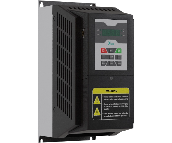
اینورتر 15 کیلووات سه فاز سری پمپ و بوستر پمپ
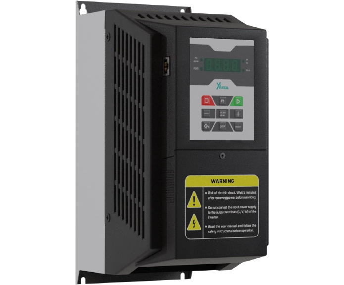
اینورتر 11 کیلووات سه فاز سری پمپ و بوستر پمپ
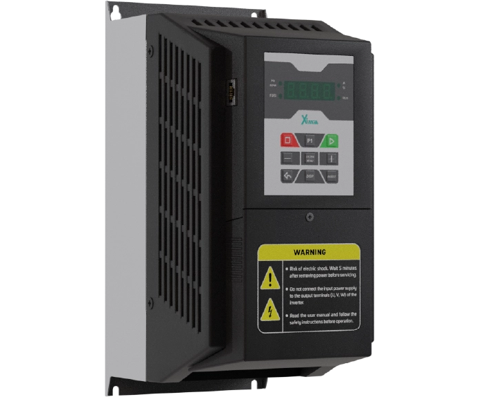
اینورتر 7.5 کیلووات سه فاز سری پمپ و بوستر پمپ
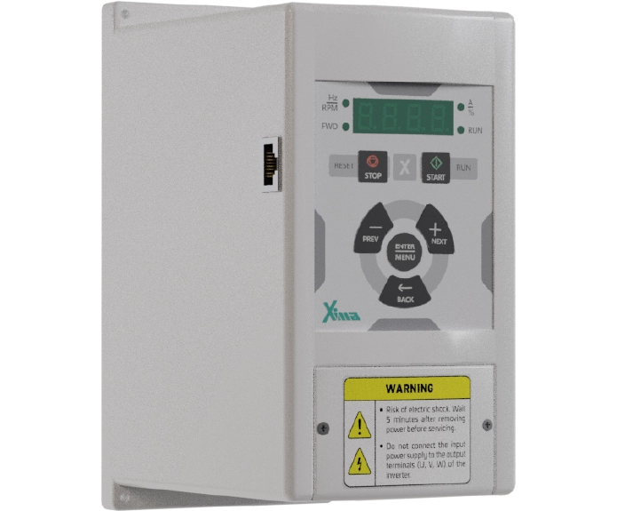
نظرات کاربران
دیدگاهها
هنوز دیدگاهی ثبت نشده است.