آموزش اتصال اینورتر به PLC با Modbus RTU | راهنمای کاربردی


اتصال اینورتر به PLC؛ راهنمای عملی راهاندازی RS485 و کنترل درایو زیما
ارتباط و اتصال اینورتر به PLC یکی از روشهای کاربردی برای کنترل و مانیتورینگ موتورهای الکتریکی در سیستمهای اتوماسیون صنعتی است. با برقراری این ارتباط، کنترلر میتواند فرمانهای کنترلی را به درایو ارسال کند و اطلاعاتی مانند فرکانس خروجی، جریان موتور، وضعیت عملکرد و خطاهای دستگاه را دریافت کند.
یکی از روشهای رایج برای این کار، استفاده از پروتکل Modbus RTU روی بستر ارتباطی RS485 است. در این روش، بهجای استفاده از سیمهای جداگانه برای تمامی فرمانها و سیگنالهای بازخورد، بخش قابلتوجهی از تبادل اطلاعات از طریق شبکه سریال انجام میشود.
در این مقاله، ابتدا اصول ارتباط اینورتر و PLC را بررسی میکنیم و سپس با استفاده از مستندات رسمی درایو صنعتی سری G زیما، نحوه سیمبندی، تنظیم پارامترهای ارتباطی، خواندن رجیسترها و عیبیابی شبکه Modbus RTU را توضیح میدهیم.
نکته ایمنی: این آموزش برای افراد آشنا با برق صنعتی و اتوماسیون تهیه شده است. نصب، سیمبندی و راهاندازی تجهیزات باید توسط فرد واجد صلاحیت و مطابق دستورالعمل سازنده انجام شود. فرمان توقف نرمافزاری یا قطع ارتباط Modbus جایگزین مدارهای ایمنی مستقل و توقف اضطراری مناسب دستگاه نیست.
ارتباط اینورتر با PLC چیست و چه کاربردی دارد؟
اینورتر یا درایو کنترل دور موتور، تجهیزی است که با کنترل پارامترهای الکتریکی خروجی، امکان تنظیم سرعت و مدیریت عملکرد موتورهای سازگار را فراهم میکند. PLC نیز کنترلری صنعتی است که بر اساس برنامه تعریفشده، ورودیها را پردازش کرده و فرمانهای لازم را به تجهیزات ارسال میکند.
وقتی این دو تجهیز با یکدیگر ارتباط برقرار میکنند، PLC میتواند مدیریت بخشی از عملکرد درایو را بر عهده بگیرد.
برای مثال، در یک سیستم نوار نقاله، PLC میتواند با توجه به شرایط فرایند، فرکانس مرجع درایو را تغییر دهد. همزمان، اطلاعات عملکرد اینورتر به کنترلر بازگردانده میشود تا وضعیت موتور در سیستم مانیتورینگ نمایش داده شود.
مهمترین کاربردهای اتصال اینورتر به PLC عبارتاند از:
- ارسال فرمانهای استارت، استپ و تغییر جهت، در صورت مجازبودن در کاربرد موردنظر
- تنظیم فرکانس مرجع و کنترل سرعت موتور
- دریافت اطلاعاتی مانند فرکانس، جریان و ولتاژ خروجی
- پایش وضعیت عملکرد و خطاهای درایو
- هماهنگسازی چند تجهیز در یک سیستم کنترلی
- انتقال اطلاعات عملکرد به HMI یا سیستم نظارت صنعتی
امکانات دقیق این ارتباط به مدل اینورتر، نسخه نرمافزار و رجیسترهایی بستگی دارد که سازنده در اختیار کاربر قرار داده است.
روشهای اتصال اینورتر به PLC
برای ایجاد ارتباط میان PLC و اینورتر، روشهای مختلفی وجود دارد. انتخاب روش مناسب به نوع کنترلر، امکانات درایو، تعداد تجهیزات، حجم اطلاعات و معماری سیستم بستگی دارد.
اتصال از طریق ورودی و خروجیهای دیجیتال
در این روش، خروجیهای دیجیتال PLC به ورودیهای کنترلی اینورتر متصل میشوند.
برای مثال، یک خروجی میتواند فرمان حرکت را ارسال کند و خروجی دیگر، بسته به تنظیمات درایو، برای انتخاب جهت یا یک عملکرد کنترلی دیگر استفاده شود.
این روش برای فرمانهای ساده مناسب است؛ اما تعداد اطلاعات قابلانتقال، به امکانات ورودی و خروجی تجهیزات محدود میشود.
اتصال از طریق سیگنال آنالوگ
در برخی سیستمها، PLC یک سیگنال آنالوگ را به ورودی مرجع اینورتر ارسال میکند.
برای نمونه، یک خروجی آنالوگ سازگار میتواند مرجع فرکانس درایو را تعیین کند. در این حالت، متناسب با مقدار سیگنال و تنظیمات ورودی آنالوگ، مرجع سرعت تغییر میکند.
این روش برای کنترل پیوسته مناسب است، اما دریافت همزمان اطلاعات متنوع از درایو معمولاً به مسیرهای ارتباطی دیگری نیاز دارد.
اتصال از طریق شبکه صنعتی Modbus RTU
در روش Modbus RTU، PLC و اینورتر اطلاعات را بهصورت پیامهای دیجیتال مبادله میکنند.
در این ساختار، کنترلر درخواست خواندن یا نوشتن اطلاعات را به آدرس دستگاه موردنظر ارسال میکند و درایو، مطابق قابلیتهای ارتباطی خود، پاسخ مناسب میدهد.
برخلاف روشهای مبتنی بر ورودی و خروجی دیجیتال یا آنالوگ، ارتباط Modbus RTU میتواند چندین فرمان و پارامتر مانیتورینگ را از طریق یک بستر ارتباطی مشترک منتقل کند.
البته این روشها الزاماً جایگزین کامل یکدیگر نیستند. در برخی پروژهها، ترکیبی از ارتباط دیجیتال، سیگنالهای آنالوگ و مدارهای ایمنی سختافزاری استفاده میشود.
پروتکل Modbus RTU چیست و چگونه کار میکند؟
Modbus یک پروتکل ارتباطی صنعتی است که امکان تبادل اطلاعات میان تجهیزات مختلف را فراهم میکند.
در ارتباط سریال Modbus RTU، معمولاً یک دستگاه نقش Master و دستگاههای دیگر نقش Slave را دارند. در مستندات جدیدتر این مفاهیم ممکن است با عنوان Client و Server نیز بیان شوند.
در پروژه اتصال اینورتر به PLC، معمولاً PLC نقش Master و درایو نقش Slave را دارد.
فرایند ارتباط به این صورت است:
- PLC درخواست خواندن یا نوشتن اطلاعات را به آدرس یک درایو ارسال میکند.
- درایو درخواست را دریافت و بررسی میکند.
- اگر فرمان معتبر باشد، عملیات مجاز انجام میشود.
- درایو، در صورت نیاز به پاسخ و مطابق نوع فرمان، نتیجه را به PLC برمیگرداند.
- برنامه PLC اطلاعات دریافتی را پردازش میکند.
در Modbus RTU، هر پیام شامل اطلاعاتی مانند آدرس دستگاه، کد عملکرد (Function Code)، دادههای مرتبط و بخش بررسی خطای ارتباطی CRC است.
تفاوت Modbus RTU و RS485 چیست؟
این دو اصطلاح گاهی بهجای یکدیگر استفاده میشوند، اما معنای یکسانی ندارند.
RS485 استانداردی برای ارتباط الکتریکی سریال است و ویژگیهای لایه فیزیکی انتقال داده را تعریف میکند.
در مقابل، Modbus RTU پروتکلی است که ساختار پیامها و شیوه تبادل اطلاعات را مشخص میکند.
به بیان ساده، RS485 بستر الکتریکی انتقال داده را فراهم میکند و Modbus RTU تعیین میکند دادهها چگونه سازماندهی و تفسیر شوند.
بنابراین، وجود پورت RS485 روی یک تجهیز بهتنهایی به معنی پشتیبانی آن از Modbus RTU نیست. پروتکل پشتیبانیشده باید در مستندات سازنده بررسی شود.
تجهیزات موردنیاز برای ارتباط PLC و اینورتر
پیش از شروع، باید مطمئن شوید تجهیزات انتخابشده از یک روش ارتباطی مشترک پشتیبانی میکنند.
برای برقراری ارتباط Modbus RTU معمولاً به تجهیزات زیر نیاز است:
- اینورتر دارای رابط RS485 و پشتیبانی مستند از Modbus RTU
- PLC دارای پورت سریال سازگار یا ماژول ارتباطی RS485
- کابل مناسب برای شبکه ارتباطی صنعتی
- تجهیزات ترمینیشن و شیلدینگ متناسب با طراحی شبکه
- دفترچه فنی PLC و اینورتر
- نرمافزار برنامهنویسی PLC برای پیکربندی و مانیتورینگ ارتباط
اگر PLC تنها پورت اترنت داشته باشد، نمیتوان آن را مستقیماً به ترمینالهای RS485 اینورتر متصل کرد. در چنین شرایطی باید از ماژول ارتباطی یا مبدل مناسب استفاده شود و سازگاری پروتکل نیز بررسی شود.
پیش از سیمبندی، مدل دقیق تجهیزات، شماره ترمینالها و روش اتصال زمین و مرجع ارتباط باید با دفترچههای رسمی تطبیق داده شوند.
آموزش سیمبندی RS485 میان PLC و اینورتر
در یک شبکه RS485 دو سیمه، انتقال داده از طریق یک زوج سیم تفاضلی انجام میشود.
نامگذاری این دو خط در تجهیزات مختلف ممکن است متفاوت باشد. بعضی سازندگان از A و B و بعضی از نشانههای مثبت و منفی استفاده میکنند.
در مستندات رسمی درایو صنعتی سری G زیما، دو ترمینال ارتباطی RS-485 با نامهای A(S+) و B(S−) معرفی شدهاند.
اتصال این ترمینالها به PLC باید مطابق نقشه سیمبندی تجهیزات و با بررسی تطابق قطبیت خطوط ارتباطی در دو سمت انجام شود.
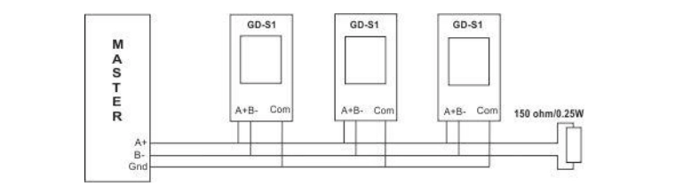
اتصال یک PLC به یک درایو
در یک ارتباط ساده، خطوط ارتباطی PLC به ترمینالهای متناظر درایو متصل میشوند.
اگر دو تجهیز از نامگذاری متفاوتی برای ترمینالهای RS485 استفاده میکنند، نباید تنها بر اساس نام A یا B سیمبندی کرد. لازم است عملکرد ترمینالها بر اساس مستندات سازنده بررسی شود.
در طراحی اتصال، نکات زیر اهمیت دارند:
- استفاده از کابل مناسب محیط صنعتی
- رعایت مسیرکشی صحیح کابل ارتباطی
- جلوگیری از عبور نامناسب کابل داده در مجاورت منابع نویز
- بررسی اتصال مرجع سیگنال و شیلد مطابق دستورالعمل تجهیزات
- انتخاب صحیح مقاومتهای انتهایی شبکه
برای بررسی صحت ارتباط، بهتر است ابتدا در یک محیط کنترلشده، یک PLC و یک درایو آزمایش شوند و سپس شبکه توسعه پیدا کند.
اتصال چند اینورتر به یک PLC
در یک شبکه چنددستگاهی، هر درایو باید آدرس ارتباطی منحصربهفرد داشته باشد.
به این ترتیب، PLC میتواند درخواستهای خود را برای دستگاه موردنظر ارسال کند.
در مستندات سری G زیما، امکان کنترل و مانیتورینگ چند درایو از طریق ارتباط Modbus RTU توضیح داده شده است. همچنین در بخش مربوط به این ارتباط، اتصال تا ۱۵ دستگاه XIMA به یک Master ذکر شده است.
بااینحال، ظرفیت واقعی شبکه باید با توجه به مدل دستگاه، مشخصات رابط، طول کابل، شرایط الکتریکی و محدودیتهای مستند تجهیزات بررسی شود.
مقاومت انتهایی شبکه RS485
یکی از عوامل مؤثر بر کیفیت ارتباط RS485، ترمینیشن صحیح خطوط داده است.
در دفترچه سری G زیما، استفاده از مقاومت ۱۵۰ اهم در انتهای مسیر ارتباطی برای کاهش انعکاس سیگنال، بهویژه در فواصل طولانی، ذکر شده است.
این مقدار یک الزام عمومی برای تمام شبکههای RS485 نیست؛ بلکه مربوط به دستورالعمل موردبررسی زیما است.
در طراحی شبکه باید مقاومتهای انتهایی دو سر مسیر، ترمینیشن احتمالی داخلی تجهیزات و نحوه بایاسکردن خطوط بررسی شوند. نصب مقاومت اضافی یا نامتناسب میتواند کیفیت ارتباط را کاهش دهد.
تنظیم پارامترهای Modbus RTU در درایو زیما سری G
برای اینکه PLC و اینورتر بتوانند با یکدیگر ارتباط برقرار کنند، تنظیمات ارتباطی دو دستگاه باید با هم سازگار باشند.
در درایو صنعتی سری G زیما، پارامترهای مربوط به ارتباط سریال در بخش پارامترهای سیستمی مستند شدهاند.
پارامترهای اصلی ارتباط Modbus در نسخه V5.2 عبارتاند از:
- 0x031B – Baud Rate: تعیین سرعت ارتباط سریال
- 0x031C – Serial Address: تعیین آدرس درایو در شبکه
- 0x031D – Parity: تعیین نوع بیت توازن
- 0x031E – Communication Time Out: تعیین زمان تشخیص قطع ارتباط
- 0x031F – Time Out Function: تعیین واکنش درایو هنگام قطع ارتباط
این آدرسها مربوط به نسخه مستندشده هستند و نباید بدون بررسی به تمام محصولات یا نسخههای نرمافزاری زیما تعمیم داده شوند.
تنظیم Baud Rate
پارامتر Baud Rate سرعت تبادل داده در ارتباط سریال را تعیین میکند.
در دفترچه سری G زیما، گزینههای زیر ثبت شدهاند:
- مقدار ۰: سرعت 4800 bps
- مقدار ۱: سرعت 9600 bps
- مقدار ۲: سرعت 19200 bps
- مقدار ۳: سرعت 38400 bps
- مقدار ۴: سرعت 57600 bps
- مقدار ۵: سرعت 115200 bps
برای برقراری ارتباط، مقدار Baud Rate در PLC و اینورتر باید یکسان باشد.
انتخاب سرعت مناسب به طول و کیفیت شبکه، شرایط نویز و توانایی سختافزار ارتباطی بستگی دارد. افزایش سرعت ارتباط لزوماً به معنی پایداری بیشتر شبکه نیست.
تنظیم آدرس ارتباطی اینورتر
پارامتر Serial Address برای مشخصکردن نشانی دستگاه در شبکه استفاده میشود.
در صورتی که دو اینورتر روی یک شبکه آدرس یکسان داشته باشند، احتمال بروز تداخل و خطای ارتباطی وجود دارد.
بنابراین، هر درایو باید یک آدرس اختصاصی داشته باشد و همان آدرس در درخواستهای PLC مورد استفاده قرار گیرد.
در دفترچه نسخه V5.2، محدوده پارامتر آدرس سریال ۱ تا ۲۴۰ درج شده است؛ بااینحال، در توضیحات بخش شبکه، محدوده ۱ تا ۲۰۰ نیز ذکر شده است. برای جلوگیری از ناسازگاری، انتخاب محدوده نهایی باید مطابق نسخه نرمافزار دستگاه و تأیید فنی سازنده باشد.
آدرس صفر در Modbus برای پیامهای Broadcast کاربرد دارد. در این حالت، دستگاههای دریافتکننده پاسخ عادی ارسال نمیکنند؛ به همین دلیل استفاده از این نوع فرمان در کاربردهای کنترلی نیازمند طراحی و بررسی دقیق است.
تنظیم Parity و بیتهای توقف
Parity یکی از تنظیمات مهم ارتباط سریال است.
در دفترچه سری G زیما سه حالت برای پارامتر 0x031D تعریف شده است:
- مقدار ۰: بدون Parity
- مقدار ۱: Parity فرد (Odd)
- مقدار ۲: Parity زوج (Even)
طبق مشخصات ارتباطی این نسخه، انتقال داده با یک بیت شروع و هشت بیت داده انجام میشود. در حالت بدون Parity، دو بیت توقف و در حالت Parity زوج یا فرد، یک بیت توقف در نظر گرفته شده است.
برای مثال، قالب 8N2 به معنی هشت بیت داده، بدون Parity و دو بیت توقف است.
هنگام تنظیم PLC باید مطمئن شوید تعداد بیتهای داده، Parity و Stop Bit دقیقاً با تنظیمات درایو تطابق دارند.
تنظیم رفتار درایو هنگام قطع ارتباط
قطع ارتباط PLC و اینورتر ممکن است به دلایلی مانند قطع کابل، نویز یا توقف برنامه ارتباطی رخ دهد.
در سری G زیما، پارامتر Communication Time Out با آدرس 0x031E زمان تشخیص این وضعیت را تعیین میکند.
پارامتر Time Out Function با آدرس 0x031F نیز واکنش درایو را مشخص میسازد.
در دفترچه، گزینههایی برای عدم انجام اقدام، توقف مطابق تنظیمات درایو و غیرفعالکردن خروجی تعریف شدهاند.
انتخاب میان این حالتها باید بر اساس ارزیابی ریسک ماشین انجام شود. برای مثال، توقف آزاد موتور ممکن است در یک کاربرد قابلقبول و در کاربردی دیگر خطرناک باشد.
تشخیص قطع ارتباط، عملکرد ایمنی دارای گواهی محسوب نمیشود و نباید جایگزین توقف اضطراری یا حفاظت مستقل دستگاه شود.
تنظیم منبع فرمان و فرکانس از طریق Modbus در سری G زیما
تنظیم پارامترهای شبکه بهتنهایی برای کنترل موتور کافی نیست. درایو باید بداند فرمان حرکت و مرجع فرکانس را از چه منبعی دریافت کند.
در مستندات سری G زیما، دو تنظیم مستقل برای این موضوع وجود دارد.
انتخاب فرمان حرکت از طریق Modbus
پارامتر Digital Input Configuration با آدرس 0x0200 نحوه دریافت فرمانهای کنترلی را تعیین میکند.
در نسخه V5.2، مقدار ۱۶ برای حالت کنترل از طریق Modbus تعریف شده است.
در این حالت، فرمانهای مرتبط با عملکرد درایو از بستر ارتباطی دریافت میشوند و رفتار بعضی ورودیهای دیجیتال نیز مطابق توضیحات دفترچه تغییر میکند.
قبل از تغییر این پارامتر باید مدار فرمان موجود، شرایط ایمنی و تأثیر تغییر منبع کنترل بر عملکرد دستگاه بررسی شود.
انتخاب مرجع فرکانس از طریق Modbus
پارامتر Analog Input Configuration با آدرس 0x0204 منبع تعیین فرکانس مرجع یا کمیت کنترلی را مشخص میکند.
در دفترچه سری G زیما، مقدار ۶ برای دریافت مرجع از طریق Modbus معرفی شده است.
بنابراین، دریافت فرمان حرکت از شبکه و دریافت مرجع فرکانس از شبکه دو موضوع جداگانه هستند.
ممکن است ارتباط سریال برقرار باشد و PLC بتواند اطلاعات درایو را بخواند، اما مرجع سرعت همچنان از ورودی دیگری دریافت شود. در چنین شرایطی، صرف ارسال مقدار فرکانس از PLC لزوماً موجب تغییر سرعت موتور نخواهد شد.
آشنایی با رجیسترهای Modbus درایو زیما
در پروتکل Modbus، اطلاعات از طریق آدرسهایی به نام Register مبادله میشوند.
هر رجیستر بسته به طراحی سازنده، ممکن است شامل مقدار یک پارامتر، وضعیت عملکرد یا فرمان کنترلی باشد.
در دفترچه سری G زیما، کد عملکرد 0x03 برای خواندن رجیسترهای پشتیبانیشده و کد 0x06 برای نوشتن یک رجیستر معرفی شده است.
پشتیبانی از این کدها نباید به معنی پشتیبانی خودکار از تمام کدهای استاندارد Modbus تلقی شود.
رجیسترهای قابلنوشتن
مهمترین رجیسترهای نوشتنی درایو سری G عبارتاند از:
- 0x2000: رجیستر فرمانهای کنترلی درایو
- 0x2001: تعیین مرجع فرکانس
- 0x2002: تعیین مرجع کنترل PID
- 0x2003: تعیین مقدار بازخورد در حالت مرتبط
در رجیستر فرمان 0x2000، بیتهای مشخصی برای عملکردهایی مانند Enable، استارت، جهت حرکت و Jog تعریف شدهاند.
برای مثال، طبق دفترچه، بیت صفر به Enable و بیت یک به فرمان استارت اختصاص دارد.
بااینحال، مقدار کامل ارسالی به این رجیستر باید بر اساس همه بیتهای مؤثر، وضعیت دستگاه و منطق کنترلی پروژه ساخته شود. ارسال یک مقدار ثابت بدون بررسی شرایط مجازبودن حرکت، روش صحیح راهاندازی ماشین نیست.
رجیسترهای خواندنی برای مانیتورینگ
درایو سری G امکان دریافت اطلاعات عملکردی از طریق رجیسترهای خواندنی را نیز فراهم میکند.
مهمترین این رجیسترها عبارتاند از:
- 0x2100: وضعیت فرمان و عملکرد دستگاه
- 0x2101: فرکانس خروجی
- 0x2102: جریان خروجی
- 0x2103: ولتاژ خروجی
- 0x2104: دمای هیتسینک
- 0x2105: توان خروجی
- 0x2106: وضعیت ترمینالها
این اطلاعات میتوانند در برنامه PLC برای نمایش وضعیت، ثبت داده و نظارت بر عملکرد سیستم استفاده شوند.
برای مثال، PLC میتواند مقدار رجیستر فرکانس خروجی را بخواند و پس از اعمال ضریب مقیاس مناسب، آن را روی HMI نمایش دهد.
نکته مهم درباره آدرسدهی رجیسترها
آدرسهایی که در دفترچه زیما آمدهاند، بهصورت Hexadecimal نمایش داده شدهاند.
در بعضی نرمافزارهای PLC، آدرس Modbus باید بهصورت آدرس خام وارد شود؛ اما در برخی دیگر، نرمافزار از قالبهای شمارهگذاری مانند Holding Register یا Offset داخلی استفاده میکند.
به همین دلیل ممکن است آدرس نمایشی در نرمافزار PLC با آدرس درجشده در دفترچه متفاوت باشد.
قبل از ارسال فرمان، باید روش آدرسدهی کتابخانه Modbus یا ماژول ارتباطی PLC بررسی شود تا درخواست به رجیستر صحیح ارسال شود.
مثال کاربردی: خواندن فرکانس اینورتر زیما با PLC
فرض کنید یک درایو سری G به PLC متصل است و هدف، نمایش فرکانس واقعی خروجی روی HMI است.
در این مثال، ابتدا فرض میکنیم ارتباط سریال بهدرستی پیکربندی شده و دستگاهها در شرایط ایمن قرار دارند.
مرحله اول: یکسانسازی تنظیمات ارتباطی
برای نمونه، میتوان سرعت ارتباط را روی 9600 bps قرار داد؛ در دفترچه این مقدار با گزینه ۱ در پارامتر 0x031B مشخص شده است.
سپس آدرس اختصاصی درایو، Parity و بیتهای توقف را انتخاب کنید و عین همین تنظیمات را در PLC اعمال کنید.
این تنظیمات نمونه هستند و به معنی بهترین پیکربندی برای همه پروژهها نیستند.
مرحله دوم: ارسال درخواست خواندن رجیستر
برای دریافت فرکانس خروجی، PLC باید درخواست Modbus را با مشخصات زیر ایجاد کند:
- آدرس Slave: آدرس اختصاصی تنظیمشده درایو
- Function Code: مقدار 0x03
- Register Address: مقدار 0x2101
- تعداد رجیستر: یک رجیستر ۱۶ بیتی
نرمافزار یا کتابخانه ارتباطی PLC باید پیام را مطابق ساختار Modbus RTU تولید کند و بخش CRC را نیز بهدرستی مدیریت کند.
مرحله سوم: تفسیر مقدار دریافتی
در مستندات زیما، فرکانس خروجی با مقیاس یک رقم اعشار ثبت میشود.
برای مثال، اگر PLC مقدار عددی ۳۵۰ را از رجیستر 0x2101 دریافت کند، مقدار فرکانس خروجی برابر است با:
۳۵۰ ÷ ۱۰ = ۳۵٫۰ هرتز
بنابراین، برنامه PLC باید مقدار خام دریافتشده را به واحد قابلفهم تبدیل کند.
این موضوع درباره سایر رجیسترها نیز اهمیت دارد؛ زیرا همه آنها الزاماً از یک ضریب مقیاس استفاده نمیکنند.
برای نمونه، در دفترچه سری G، جریان خروجی با مقیاس یک رقم اعشار و ولتاژ خروجی بدون اعشار معرفی شده است.
مرحله چهارم: نمایش مقدار روی HMI
پس از تبدیل مقدار، میتوان آن را در یک متغیر عددی ذخیره و به صفحه نمایش HMI منتقل کرد.
بهتر است علاوه بر فرکانس، وضعیت ارتباط نیز نمایش داده شود تا در صورت قطع شبکه یا نامعتبرشدن داده، آخرین مقدار دریافتی بهاشتباه بهعنوان اطلاعات لحظهای نمایش داده نشود.
مثال کاربردی: تنظیم فرکانس اینورتر از طریق PLC
یکی دیگر از کاربردهای Modbus، ارسال مرجع فرکانس به درایو است.
در دفترچه رسمی سری G زیما، رجیستر 0x2001 برای این منظور معرفی شده است.
مقدار فرکانس باید با مقیاس مستند دستگاه ارسال شود. برای مثال، طبق دفترچه، مقدار ۵۰٫۰ هرتز بهصورت عدد صحیح ۵۰۰ در رجیستر قرار میگیرد.
مشخصات مفهومی چنین درخواستی عبارتاند از:
- Function Code: مقدار 0x06
- Register Address: مقدار 0x2001
- مقدار داده نمونه: عدد ۵۰۰
- مفهوم مقدار: مرجع فرکانس ۵۰٫۰ هرتز
این مثال فقط شیوه نمایش داده در رجیستر را توضیح میدهد. مقدار ۵۰ هرتز یک تنظیم پیشنهادی عمومی برای همه موتورها نیست.
پیش از ارسال واقعی فرمان باید مطمئن شوید:
- موتور و درایو برای شرایط کاری انتخابشده مناسباند.
- حدود فرکانس و شتابگیری بهدرستی تنظیم شدهاند.
- منبع فرکانس در درایو روی Modbus قرار گرفته است.
- منطق فرمان حرکت و توقف ایمن طراحی شده است.
- وضعیت عملکرد و خطاهای درایو در PLC بررسی میشود.
نکته: نوشتن مرجع فرکانس با ارسال فرمان استارت متفاوت است. دریافت موفق فرمان نوشتن نیز بهتنهایی ثابت نمیکند که موتور به فرکانس هدف رسیده است. این موضوع باید از طریق رجیسترهای مانیتورینگ کنترل شود.
تفاوت ارسال فرمان و دریافت وضعیت در ارتباط PLC و اینورتر
یکی از اشتباهات رایج در برنامهنویسی اتصال اینورتر به PLC، یکسان در نظر گرفتن مقدار فرمان با وضعیت واقعی دستگاه است.
برای مثال، PLC ممکن است مرجع فرکانس مشخصی را به درایو ارسال کند، اما موتور هنوز در حال شتابگیری باشد.
در این شرایط، مقدار درخواستی با فرکانس خروجی واقعی یکسان نیست.
برای طراحی یک سیستم مانیتورینگ قابلاعتماد، بهتر است سه نوع اطلاعات از یکدیگر تفکیک شوند:
۱. مقدار فرمان: مقداری که PLC برای کنترل دستگاه ارسال کرده است.
۲. مقدار واقعی: اطلاعاتی که از رجیسترهای مانیتورینگ درایو دریافت میشود.
۳. وضعیت ارتباط و دستگاه: اطلاعاتی که مشخص میکند پاسخ دریافتی معتبر بوده و دستگاه در چه وضعیتی قرار دارد.
این تفکیک بهویژه در سیستمهایی اهمیت دارد که اطلاعات اینورتر برای تصمیمهای کنترلی بعدی استفاده میشوند.
خطاهای رایج ارتباط اینورتر با PLC و روش عیبیابی
در راهاندازی Modbus RTU ممکن است ارتباط از ابتدا برقرار نشود یا پس از مدتی دچار اختلال شود.
برای عیبیابی صحیح، ابتدا باید مشخص شود مشکل در کدام بخش قرار دارد: سیمبندی، تنظیمات سریال، آدرسدهی، ساختار درخواست یا منطق کنترل.
۱. PLC هیچ پاسخی از اینورتر دریافت نمیکند
اگر تمام درخواستها بدون پاسخ بمانند، ابتدا وضعیت فیزیکی شبکه و تنظیمات ارتباطی را بررسی کنید.
موارد مهم عبارتاند از:
- صحیحبودن اتصال ترمینالهای RS485
- یکسانبودن Baud Rate دو دستگاه
- تطابق Parity و Stop Bit
- صحیحبودن آدرس Slave
- فعالبودن پورت ارتباطی و برنامه Master
- بررسی کیفیت کابل و نحوه ترمینیشن
بهتر است در شروع عیبیابی از یک درخواست خواندن ساده، مانند خواندن رجیستر مانیتورینگ، استفاده شود.
۲. ارتباط برقرار است، اما فرکانس تغییر نمیکند
در چنین وضعیتی ممکن است PLC بتواند اطلاعات درایو را بخواند، اما منبع فرکانس همچنان روی ورودی دیگری تنظیم شده باشد.
در سری G زیما، باید وضعیت پارامتر Analog Input Configuration و انتخاب مرجع Modbus بررسی شود.
همچنین باید مطمئن شوید آدرس رجیستر، کد عملکرد و مقدار داده ارسالی با مستندات سازگار هستند.
۳. فرمان استارت ارسال میشود، اما موتور حرکت نمیکند
دریافت پیام توسط اینورتر به معنی مجازبودن حرکت موتور نیست.
در این حالت، علاوه بر تنظیم منبع فرمان، لازم است وضعیت Enable، خطاهای فعال، محدودیتهای کنترلی و شرایط مجازبودن راهاندازی بررسی شود.
در رجیستر وضعیت 0x2100 سری G زیما، اطلاعاتی درباره Enable، استارت، جهت حرکت و وضعیتهای عملکردی دستگاه ثبت میشود.
از این دادهها میتوان برای تشخیص بهتر شرایط دستگاه استفاده کرد؛ اما وضعیتهای ایمنی مستقل باید از مسیرهای مناسب خود ارزیابی شوند.
۴. ارتباط بهصورت متناوب قطع میشود
قطعووصل ارتباط معمولاً نیازمند بررسی چند عامل است:
- نویز الکترومغناطیسی محیط
- کابل نامناسب یا آسیبدیده
- مسیرکشی نامطلوب کابل داده
- ترمینیشن و بایاس نامناسب
- تنظیم نادرست زمان انتظار پاسخ
- تعداد زیاد درخواستها نسبت به ظرفیت ارتباط
- مشکلات مرجع ولتاژ مشترک میان دستگاهها
برای پیدا کردن علت، تغییرات باید مرحلهبهمرحله انجام شوند تا تأثیر هر اصلاح قابلارزیابی باشد.
۵. درایو پیام خطای Modbus برمیگرداند
در دفترچه سری G زیما، خطاهای پاسخ Modbus از جمله موارد زیر توضیح داده شدهاند:
- کد ۱: کد عملکرد درخواستشده معتبر یا پشتیبانیشده نیست.
- کد ۲: آدرس رجیستر نامعتبر است.
- کد ۳: مقدار ارسالی خارج از محدوده مجاز است.
- کد ۴: اجرای عملیات درخواستی امکانپذیر نیست.
برای مثال، تلاش برای نوشتن در یک رجیستر فقطخواندنی میتواند موجب پاسخ خطا شود.
در برنامه PLC باید این پاسخها از قطع کامل ارتباط تفکیک شوند؛ زیرا دریافت پاسخ خطا نشان میدهد که دستگاه پیام را دریافت کرده، اما درخواست را نپذیرفته است.
نکات مهم برای طراحی ارتباط پایدار بین PLC و اینورتر
برقراری اولین ارتباط موفق، پایان کار نیست. سیستم باید در شرایط واقعی بهرهبرداری نیز عملکرد قابلاعتمادی داشته باشد.
در طراحی شبکه و برنامه PLC به نکات زیر توجه کنید.
ابتدا با خواندن اطلاعات ارتباط اینورتر با PLC را آزمایش کنید
بهتر است پیش از فعالکردن فرمانهای حرکتی، ارتباط با خواندن رجیسترهای مانیتورینگ بررسی شود.
این کار کمک میکند مشکلات مربوط به آدرسدهی و تنظیمات سریال، بدون ارسال فرمان حرکت، شناسایی شوند.
زمان پاسخ و خطای ارتباطی را مدیریت کنید
در برنامه PLC باید شرایطی مانند دریافت پاسخ معتبر، تأخیر پاسخ، خطای پروتکل و قطع ارتباط از یکدیگر تفکیک شوند.
تعداد دفعات تلاش مجدد و فاصله درخواستها نیز باید متناسب با ظرفیت شبکه انتخاب شود.
از آدرسدهی تکراری جلوگیری کنید
در شبکهای با چند درایو، یکسانبودن آدرس دو دستگاه میتواند باعث اختلال در تبادل اطلاعات شود.
ثبت آدرسها در نقشه شبکه و مستندات پروژه، عیبیابی و توسعه آینده سیستم را سادهتر میکند.
شرایط ایمنی را مستقل از ارتباط در نظر بگیرید
Modbus RTU برای تبادل اطلاعات کنترلی و مانیتورینگ استفاده میشود. این ارتباط بهخودیخود یک سیستم ایمنی عملکردی نیست.
در تجهیزاتی که حرکت ناخواسته میتواند خطر ایجاد کند، منطق توقف اضطراری، حفاظت افراد و پیشگیری از راهاندازی ناخواسته باید مطابق ارزیابی ریسک و الزامات مربوط طراحی شود.
نسخه مستندات را با دستگاه تطبیق دهید
ممکن است مدلهای مختلف اینورتر یا نسخههای نرمافزاری متفاوت، تنظیمات یکسانی نداشته باشند.
به همین دلیل، پیش از تغییر پارامترها باید مدل دقیق درایو و نسخه مستندات مورد استفاده مشخص شود.
ارتباط Modbus RTU در درایو صنعتی سری G زیما
درایو صنعتی سری G زیما از قابلیت ارتباط سریال RS485 با پروتکل Modbus RTU برخوردار است؛ قابلیتی که در راهنمای رسمی نصب این سری مستند شده است.
بر اساس این راهنما، امکان ارسال فرمانهای کنترلی و دریافت اطلاعات عملکردی از طریق شبکه وجود دارد.
از جمله اطلاعاتی که در بخش رجیسترهای خواندنی این نسخه معرفی شدهاند، میتوان به وضعیت فرمان، فرکانس خروجی، جریان، ولتاژ، دمای هیتسینک و توان خروجی اشاره کرد.
همچنین تنظیمات مربوط به سرعت ارتباط، آدرس سریال، Parity و مدیریت قطع ارتباط در بخش پارامترهای سیستمی دستگاه ارائه شدهاند.
برای مشاهده اطلاعات محصولات و دریافت مستندات رسمی، میتوانید به صفحه درایو صنعتی سری G زیما و مرکز دانلود زیما مراجعه کنید.
راهنمای فنی مورد استناد این مقاله نیز با عنوان راهنمای نصب درایو زیما سری صنعتی G، نسخه V5.2 در وبسایت زیما منتشر شده است.
سؤالات متداول درباره اتصال اینورتر به PLC
آیا میتوان هر اینورتری را از طریق Modbus RTU به PLC متصل کرد؟
خیر. اینورتر باید از Modbus RTU پشتیبانی کند و رابط ارتباطی سازگار داشته باشد. وجود پورت RS485 بهتنهایی برای تأیید پشتیبانی از این پروتکل کافی نیست.
آیا برای اتصال اینورتر به PLC حتماً به ماژول ارتباطی نیاز داریم؟
اگر PLC دارای پورت RS485 و قابلیت اجرای نقش Master در Modbus RTU باشد، ممکن است به ماژول جداگانه نیازی نباشد. در غیر این صورت، انتخاب ماژول یا مبدل مناسب به سختافزار و امکانات کنترلر بستگی دارد.
چرا PLC به اینورتر متصل میشود، اما فرمان استارت اجرا نمیشود؟
ممکن است منبع فرمان درایو درست تنظیم نشده باشد، شرایط Enable برقرار نباشد یا دستگاه خطای فعال داشته باشد. در چنین شرایطی باید تنظیمات منبع فرمان، وضعیت رجیسترها و منطق کنترلی پروژه بررسی شود.
تفاوت Modbus RTU و Modbus TCP چیست؟
Modbus RTU معمولاً برای ارتباط سریال، از جمله روی بستر RS485، استفاده میشود. Modbus TCP برای تبادل پیامهای Modbus در شبکههای مبتنی بر TCP/IP طراحی شده است. این دو از نظر بستر انتقال و ساختار ارتباطی یکسان نیستند و اتصال آنها ممکن است به تجهیزات واسط نیاز داشته باشد.
آیا میتوان با Modbus RTU فرکانس اینورتر زیما را تغییر داد؟
طبق راهنمای سری G زیما، امکان تعیین مرجع فرکانس از طریق Modbus وجود دارد. برای استفاده از این قابلیت، علاوه بر ارسال مقدار به رجیستر مربوط، باید منبع فرکانس نیز متناسب با کنترل از طریق شبکه تنظیم شده باشد.
آیا قطع ارتباط PLC باعث توقف خودکار اینورتر میشود؟
این موضوع به تنظیمات دستگاه بستگی دارد. در سری G زیما، پارامترهایی برای تعیین زمان تشخیص قطع ارتباط و واکنش دستگاه تعریف شدهاند. انتخاب رفتار مناسب باید بر اساس شرایط فرایند و الزامات ایمنی انجام شود.
جمعبندی ارتباط اینورتر با PLC
ارتباط اینورتر با PLC از طریق Modbus RTU، روشی برای تبادل دیجیتال فرمانها و اطلاعات عملکردی در سیستمهای اتوماسیون صنعتی است. با استفاده از این ارتباط میتوان، در محدوده امکانات هر دستگاه، فرکانس مرجع را تنظیم کرد، وضعیت کارکرد را دریافت کرد و اطلاعات موردنیاز برای مانیتورینگ را در اختیار کنترلر قرار داد.
برای پیادهسازی صحیح روند ارتباط اینورتر با PLC، سه موضوع اهمیت ویژه دارند: سیمبندی اصولی RS485، تطابق تنظیمات سریال و استفاده درست از رجیسترهای مستند سازنده.
در درایو صنعتی سری G زیما، تنظیمات و آدرسهای ارتباطی موردنیاز در راهنمای رسمی دستگاه ارائه شدهاند. استفاده از این مستندات در کنار طراحی صحیح برنامه PLC، میتواند فرایند راهاندازی، عیبیابی و نگهداری سیستم را منظمتر کند.
برای بررسی مدل مناسب درایو و دریافت اطلاعات فنی معتبر، به بخش محصولات صنعتی زیما مراجعه کنید. همچنین برای دریافت راهنمای تخصصی درباره انتخاب و راهاندازی تجهیزات، میتوانید از طریق صفحه ارتباط با زیما با مجموعه در ارتباط باشید.
Connecting an inverter (VFD) to a PLC using Modbus RTU is an effective way to control, monitor, and automate electric motors in industrial applications. By establishing communication between a Programmable Logic Controller (PLC) and a Variable Frequency Drive (VFD), operators can send control commands, adjust motor speed, and retrieve operating data without relying on separate wiring for every control and feedback signal.
One of the most widely used methods for PLC-to-VFD communication is Modbus RTU over RS-485. This serial communication method allows industrial controllers to exchange information with compatible motor drives through a shared communication network.
In this guide, we explain how to connect an inverter to a PLC, configure RS-485 communication, set Modbus RTU parameters, read and write registers, and troubleshoot common communication problems.
The practical examples are based on the XIMA G Series industrial VFD, using the manufacturer’s official installation manual, Version V5.2 (software version H3.24).
Safety Notice: This guide is intended for qualified personnel familiar with industrial electrical systems and automation. Wiring, commissioning, and motor operation must follow the manufacturer’s instructions and applicable safety requirements. Software stop commands and Modbus communication failures must never be considered substitutes for independent emergency-stop systems or appropriate machine safety circuits.
What Is PLC-to-Inverter Communication?
A Variable Frequency Drive (VFD), also known as a motor inverter, controls the operating speed of a compatible AC motor by adjusting its output frequency and voltage.
A Programmable Logic Controller (PLC) is an industrial controller that processes input signals and executes programmed instructions to control machinery and industrial processes.
When an inverter and a PLC communicate, the PLC can control selected drive functions and monitor operating conditions through the communication interface.
For example, in a conveyor system, the PLC can adjust the inverter’s frequency reference according to production requirements. At the same time, the VFD can transmit information such as output frequency, current, and operating status back to the controller.
Main Benefits of Connecting a VFD to a PLC
PLC-to-VFD communication supports several industrial automation functions:
- Sending start, stop, and direction commands when permitted by the application.
- Adjusting the motor’s frequency reference and operating speed.
- Reading output frequency, current, and voltage.
- Monitoring drive status and fault conditions.
- Coordinating multiple motor drives within one control system.
- Transferring operating information to an HMI or industrial monitoring platform.
The exact capabilities depend on the VFD model, firmware version, supported communication functions, and available registers.
Methods of Connecting an Inverter to a PLC
There are several ways to establish communication or control between a PLC and an inverter.
The appropriate method depends on the controller, drive capabilities, required control functions, number of devices, and overall system architecture.
1. Digital Input and Output Connection
In this method, the PLC’s digital outputs connect directly to the inverter’s digital control inputs.
For example, one output may provide the run command, while another may select motor direction or activate a different control function, depending on the VFD configuration.
Digital I/O connections are suitable for relatively simple control systems. However, the number of signals that can be exchanged is limited by the available hardware inputs and outputs.
2. Analog Signal Connection
Some industrial control systems use an analog output from the PLC to provide the inverter’s speed reference.
Depending on the equipment, a compatible analog signal can be used to adjust the frequency reference continuously.
This approach is useful for variable-speed applications, but obtaining detailed operating data from the drive may require additional communication channels.
3. Modbus RTU Communication
With Modbus RTU, the PLC and inverter exchange digital messages through a serial communication network.
Instead of dedicating individual wires to multiple commands and feedback signals, the PLC can send requests to read or write supported drive registers.
This allows multiple control and monitoring functions to be handled through a common communication interface.
Modbus communication does not necessarily eliminate the need for digital inputs, analog signals, or independent safety wiring. Many industrial systems combine these methods.
What Is Modbus RTU and How Does It Work?
Modbus RTU is an industrial serial communication protocol used to exchange information between compatible automation devices.
In a typical Modbus RTU network, one device operates as the Master, while the connected devices operate as Slaves.
Modern documentation may also use the terms Client and Server.
When connecting a PLC to an inverter:
- The PLC typically acts as the Modbus Master.
- The VFD operates as a Modbus Slave.
- The PLC sends requests to a specific device address.
- The inverter processes supported requests and returns the appropriate response.
How Modbus RTU Communication Works
A typical communication sequence follows these steps:
- The PLC sends a read or write request to the inverter’s Slave address.
- The inverter receives and checks the request.
- If the command is valid and permitted, the requested operation is performed.
- The inverter returns the relevant response when required by the protocol.
- The PLC processes the received information.
Modbus RTU messages contain fields such as the device address, Function Code, associated data, and a Cyclic Redundancy Check (CRC) for communication error detection.
Modbus RTU vs. RS-485: What Is the Difference?
Although Modbus RTU and RS-485 are frequently mentioned together, they are not the same technology.
RS-485 defines electrical characteristics for serial data transmission. It provides the physical communication interface used by compatible industrial devices.
Modbus RTU is a communication protocol that defines how messages are organized, transmitted, and interpreted.
In simple terms:
- RS-485 provides the electrical communication medium.
- Modbus RTU defines the structure and meaning of exchanged messages.
An RS-485 interface does not automatically guarantee Modbus RTU support. The supported protocol must be confirmed in the equipment documentation.
Equipment Required for PLC-to-VFD Modbus RTU Communication
Before starting the installation, make sure both devices support a compatible communication method.
The typical requirements include:
- A VFD equipped with an RS-485 interface and documented Modbus RTU support.
- A PLC with an RS-485 communication port or compatible communication module.
- A suitable industrial communication cable.
- Appropriate shielding and termination arrangements.
- The technical manuals for both the PLC and VFD.
- PLC programming software for configuring, testing, and monitoring communication.
If the PLC only has an Ethernet interface, it cannot be directly wired to the inverter’s RS-485 terminals.
In that case, a compatible communication module or gateway is required, and protocol compatibility must also be verified.
Before wiring, identify the exact device models, communication terminal labels, reference connections, and grounding requirements.
How to Wire RS-485 Between a PLC and an Inverter
RS-485 communication is commonly implemented using a two-wire differential data pair.
The two signal lines may be identified differently by equipment manufacturers. Some use A and B, while others use positive and negative signal designations.
According to the official XIMA G Series VFD documentation, the RS-485 communication terminals are identified as:
- A(S+)
- B(S−)
The wiring must follow the manufacturer’s terminal diagram and verified signal polarity at both devices.
Connecting One PLC to One VFD
For a basic point-to-point connection, the PLC’s RS-485 communication terminals are connected to the corresponding communication terminals on the inverter.
However, terminal names should not be matched solely by the letters A and B.
RS-485 terminal naming conventions can vary between manufacturers. Always confirm the electrical signal definitions in the manuals for both devices.
Important installation considerations include:
- Use communication cable suitable for the industrial environment.
- Route communication cables appropriately.
- Avoid unsuitable routing near high-noise power circuits.
- Follow the manufacturer’s instructions for signal common, grounding, and shielding.
- Select and install line termination correctly.
- Verify the wiring before applying control commands.
For initial testing, establish communication between one PLC and one drive under controlled conditions before expanding the network.
Connecting Multiple VFDs to One PLC
Modbus RTU also supports communication with multiple compatible drives on a shared network.
In a multi-drive installation, every inverter must have a unique Slave address.
The PLC can then direct read and write requests to the required device.
The XIMA G Series manual describes communication between a Master and multiple XIMA drives, including an arrangement with up to 15 devices connected to one Master.
The actual supported network configuration must be checked against the relevant device models, communication interface limitations, cable length, electrical conditions, and manufacturer specifications.
RS-485 Termination Resistors
Correct termination helps minimize signal reflections and improve communication reliability.
The XIMA G Series V5.2 manual specifies a 150-ohm termination resistor in its RS-485 communication arrangement, particularly for longer communication lines.
This value is associated with the referenced XIMA documentation and should not be interpreted as a universal requirement for every RS-485 network.
When designing the network, check:
- Termination at the ends of the communication bus.
- Any internal termination already present in connected devices.
- The required line-biasing arrangement.
- The electrical characteristics and installation conditions of the network.
Incorrect or excessive termination can reduce communication reliability.
Configuring Modbus RTU Parameters on a XIMA G Series VFD
For successful communication, the inverter and PLC must use compatible serial communication settings.
The XIMA G Series V5.2 manual documents the relevant Modbus parameters in its system parameter section.
Main Modbus RTU Parameters
| Parameter | Register Address | Function |
|---|---|---|
| SE28 | 0x031B |
Baud Rate |
| SE29 | 0x031C |
Serial Address |
| SE30 | 0x031D |
Parity |
| SE31 | 0x031E |
Communication Timeout |
| SE32 | 0x031F |
Timeout Function |
These parameters correspond to the referenced manual version. They must not be applied to other XIMA drive models or firmware versions without checking their respective documentation.
1. Setting the Baud Rate
The Baud Rate determines the serial data transmission speed.
The XIMA G Series manual lists the following settings:
| Parameter Value | Baud Rate |
|---|---|
| 0 | 4800 bps |
| 1 | 9600 bps |
| 2 | 19200 bps |
| 3 | 38400 bps |
| 4 | 57600 bps |
| 5 | 115200 bps |
The documented default value is 38400 bps, corresponding to parameter value 3.
The PLC and VFD must be configured with matching Baud Rates.
The appropriate communication speed depends on cable length, network quality, electromagnetic interference, and hardware capabilities.
Higher Baud Rates do not automatically provide greater communication reliability.
2. Setting the Modbus Slave Address
The Serial Address identifies an individual inverter on the Modbus network.
If two drives use the same Slave address, communication conflicts may occur.
Each drive should therefore have a unique address, and the PLC must use that same address when sending requests.
In the XIMA G Series V5.2 manual, the serial address parameter table specifies a range of 1 to 240. However, the communication section also refers to a range of 1 to 200.
Because these ranges differ within the documentation, the applicable limit should be confirmed for the installed firmware and hardware version.
Modbus address 0 is reserved for broadcast messages. Devices receiving a broadcast request do not return normal individual responses.
Broadcast commands therefore require careful consideration in motor-control applications.
3. Configuring Parity and Stop Bits
Parity is another essential serial communication setting.
The XIMA G Series manual defines three options for register 0x031D:
| Value | Parity Mode |
|---|---|
| 0 | None |
| 1 | Odd |
| 2 | Even |
According to the V5.2 communication specifications, the serial frame uses one start bit and eight data bits.
When parity is disabled, two stop bits are used.
When Odd or Even parity is selected, one stop bit is used.
For example, 8N2 means:
- 8 data bits.
- No parity.
- 2 stop bits.
With the documented default settings, the serial configuration is 38400 bps, no parity, and two stop bits.
The PLC must use matching data-bit, parity, and stop-bit settings.
4. Configuring Communication Timeout Behavior
Communication between a PLC and an inverter may be interrupted by a damaged cable, electromagnetic interference, or failure of the communication program.
On the XIMA G Series VFD, register 0x031E defines the Communication Timeout period.
Register 0x031F determines the drive’s response when the communication timeout condition occurs.
The documented options include:
- Taking no additional action.
- Stopping the drive according to its configured stopping behavior.
- Disabling the drive output.
The correct response depends on the application and machine risk assessment.
For example, allowing a motor to coast to a stop may be acceptable in one application but hazardous in another.
Important: Communication timeout detection is not a certified functional safety mechanism and must not replace independent emergency-stop or machine-protection functions.
Selecting Modbus as the Command and Frequency Source
Configuring the serial communication parameters alone is not sufficient to control motor operation.
The inverter must also be configured to accept the appropriate commands and frequency reference from the Modbus interface.
The XIMA G Series provides separate settings for these functions.
Selecting Modbus for Run and Stop Commands
The Digital Input Configuration parameter determines the source of certain drive control commands.
In the referenced XIMA G Series manual:
- Parameter:
io01 - Register Address:
0x0200 - Modbus Control Setting:
16
When this setting is selected, the relevant control commands can be received through the Modbus communication interface.
Before modifying the parameter, inspect the existing control circuit, safety conditions, and the effects of switching the command source.
Selecting Modbus as the Frequency Reference
The Analog Input Configuration parameter determines the source of the drive’s frequency reference or associated control quantity.
For the referenced XIMA G Series version:
- Parameter:
io05 - Register Address:
0x0204 - Modbus Frequency Reference Setting:
6
Receiving run commands through Modbus and receiving the frequency reference through Modbus are two separate functions.
It is possible for the PLC to communicate with the inverter successfully while the drive continues to use a different frequency reference source.
In that situation, writing a new frequency value from the PLC may not change the motor’s operating speed.
Understanding XIMA VFD Modbus Registers
Modbus communication uses register addresses to exchange control and monitoring data.
Depending on the manufacturer and register definition, an address may represent a drive parameter, an operating value, a status word, or a control command.
The XIMA G Series manual documents the following Function Codes for the relevant operations:
- Function Code
0x03: Read supported registers. - Function Code
0x06: Write a single register.
Support for these functions does not automatically mean the drive supports every Modbus Function Code.
Writable Modbus Registers
The principal writable registers documented for the XIMA G Series include:
| Register | Description |
|---|---|
0x2000 |
Drive control commands |
0x2001 |
Frequency reference |
0x2002 |
PID reference |
0x2003 |
Associated feedback value |
The control register 0x2000 contains individual bits assigned to functions such as Enable, Start, direction selection, and Jog.
For example, the manual identifies:
- Bit 0: Enable
- Bit 1: Start
The complete control word must be constructed according to the drive state, other relevant bits, and the machine’s control logic.
Writing a fixed control word without verifying the permitted operating conditions is not an appropriate method of commissioning machinery.
Readable Modbus Registers
The XIMA G Series also provides registers for monitoring drive operation.
| Register | Monitored Information |
|---|---|
0x2100 |
Command and operating status |
0x2101 |
Output frequency |
0x2102 |
Output current |
0x2103 |
Output voltage |
0x2104 |
Heatsink temperature |
0x2105 |
Output power |
0x2106 |
Terminal status |
These values can be used in the PLC program for monitoring, data logging, and displaying information on an HMI.
For example, the PLC can read the output frequency register and convert its raw value into hertz using the documented scaling factor.
Important Note About Modbus Register Addressing
The XIMA manual presents register addresses in hexadecimal format.
However, PLC software packages do not always use the same register-addressing conventions.
Some require the raw Modbus address, while others use Holding Register numbering or internal offsets.
For this reason, the address displayed in the PLC programming environment may differ from the address printed in the drive manual.
Before sending commands, verify the addressing convention used by the specific PLC communication library or Modbus module.
Practical Example: Reading VFD Output Frequency with a PLC
Consider a XIMA G Series inverter connected to a PLC through Modbus RTU.
The objective is to read the actual output frequency and display it on an HMI.
This example assumes that serial communication has already been configured and the equipment is in a safe operating condition.
Step 1: Match the Communication Settings
First, ensure that the PLC and VFD use compatible communication settings.
For demonstration purposes, a Baud Rate of 9600 bps may be selected.
In the XIMA G Series documentation, this corresponds to parameter value 1 at register 0x031B.
Next, configure the Slave address, Parity, and Stop Bits consistently on both devices.
These are example settings, not a universal recommendation for all installations.
Step 2: Send a Register Read Request
To read the inverter’s output frequency, the PLC creates a Modbus request with the following information:
| Request Field | Value |
|---|---|
| Slave Address | Configured inverter address |
| Function Code | 0x03 |
| Register Address | 0x2101 |
| Quantity | One 16-bit register |
The PLC software or Modbus communication library must generate the appropriate RTU message and handle CRC calculation correctly.
Step 3: Convert the Received Value
According to the XIMA G Series documentation, the output frequency value uses a scaling factor of 10.
For example, suppose the PLC reads the integer value 350 from register 0x2101.
The actual output frequency is calculated as:
350 ÷ 10 = 35.0 Hz
The PLC program should convert the raw register value before displaying it as an engineering unit.
Other registers may use different scaling factors.
For example, the referenced manual indicates a one-decimal-place representation for output current, while the output voltage is represented without decimal places.
Step 4: Display the Frequency on the HMI
After converting the value, the PLC can store it in a suitable variable and display it on an HMI.
The HMI should also indicate communication validity.
If the network disconnects or the received data becomes invalid, the last recorded frequency should not continue to appear as a current live measurement without an appropriate warning.
Practical Example: Setting VFD Frequency Through a PLC
Another important application of Modbus RTU is sending the frequency reference from a PLC to an inverter.
According to the official XIMA G Series documentation, register 0x2001 is used for the frequency reference.
The value must be transmitted using the scaling specified by the manufacturer.
For example, a frequency reference of 50.0 Hz is represented by the integer value 500.
The conceptual Modbus request is:
| Request Field | Value |
|---|---|
| Function Code | 0x06 |
| Register Address | 0x2001 |
| Example Data Value | 500 |
| Corresponding Reference | 50.0 Hz |
This example illustrates register scaling only.
A 50 Hz reference is not an appropriate universal operating setting for every motor or application.
Before sending an actual control command, verify that:
- The motor and inverter are correctly selected for the application.
- Frequency limits and acceleration settings are appropriate.
- Modbus is selected as the drive’s frequency reference source.
- The run and stop control logic has been designed safely.
- The PLC monitors relevant operating conditions and drive faults.
Important: Writing a frequency reference is different from sending a Start command.
A successful Modbus write response also does not prove that the motor has reached the requested frequency.
Actual operation must be verified through the appropriate monitoring registers.
Difference Between VFD Commands and Actual Operating Status
A common mistake in PLC-to-VFD communication is treating a control command as confirmation of actual drive operation.
For example, the PLC may send a 40 Hz frequency reference while the motor is still accelerating.
During this period, the requested frequency and actual output frequency are different.
For reliable monitoring, three types of information should be distinguished:
- Command value: The control value transmitted by the PLC.
- Actual value: The operating value read from the inverter’s monitoring registers.
- Communication and drive status: Information indicating whether the response is valid and what state the inverter is currently in.
This distinction is particularly important when VFD feedback is used for subsequent control decisions.
Common PLC-to-VFD Modbus RTU Problems and Troubleshooting
Modbus RTU communication may fail during initial commissioning or become unstable after the system has been operating.
A structured troubleshooting process helps determine whether the problem involves wiring, communication settings, register addressing, message structure, or drive control logic.
1. The PLC Receives No Response from the VFD
If all Modbus requests time out, begin by checking the physical communication interface and serial settings.
Verify the following:
- Correct RS-485 terminal connections.
- Matching Baud Rates.
- Matching Parity and Stop Bit settings.
- Correct Modbus Slave address.
- Active PLC communication port and Master program.
- Suitable communication cable and termination.
Start troubleshooting with a simple read request to a supported monitoring register before sending motor-control commands.
2. Modbus Communication Works, but the Frequency Does Not Change
In this situation, the PLC may be able to read inverter data while the frequency reference is still assigned to another input source.
For the XIMA G Series, check the Analog Input Configuration parameter and confirm that the Modbus frequency reference option is selected.
Also verify the register address, Function Code, and transmitted data value.
3. The Start Command Is Sent, but the Motor Does Not Run
Receiving a Modbus command does not automatically mean that the motor is permitted to start.
In addition to checking the command source, verify:
- Drive Enable status.
- Active fault conditions.
- Relevant drive control limitations.
- Permissive conditions required for motor operation.
Register 0x2100 contains command and operating status information for the referenced XIMA G Series.
These values can assist troubleshooting, but independent machine safety conditions must still be evaluated through the appropriate safety systems.
4. RS-485 Communication Disconnects Intermittently
Intermittent communication problems may be caused by several factors:
- Electromagnetic interference.
- Damaged or unsuitable communication cable.
- Poor cable routing.
- Incorrect termination or line biasing.
- Inappropriate PLC response timeout settings.
- Excessive request frequency relative to network capacity.
- Signal reference or common-mode voltage problems.
Make changes systematically and test the effect of each correction.
5. The VFD Returns a Modbus Exception Response
The XIMA G Series documentation describes Modbus exception conditions including the following:
| Exception Code | Meaning |
|---|---|
| 01 | Unsupported or invalid Function Code |
| 02 | Invalid register address |
| 03 | Register value outside the allowed range |
| 04 | Requested operation cannot be completed |
For example, attempting to write to a read-only register may result in an exception response.
The PLC program should distinguish exception responses from communication timeouts.
An exception response means that the drive received the message but could not accept or execute the requested operation.
Best Practices for Reliable PLC-to-VFD Modbus RTU Communication
Establishing the first successful communication response is only the beginning.
The system must also operate reliably under normal industrial conditions.
Test Communication Before Enabling Motor Commands
Begin by reading a supported monitoring register.
This helps identify serial communication and addressing issues without issuing motion commands.
Handle Communication Timeouts and Errors
The PLC program should distinguish between:
- Valid responses.
- Delayed responses.
- Modbus exception responses.
- Complete loss of communication.
Retry limits and request intervals should be selected according to the communication network’s capabilities.
Avoid Duplicate Slave Addresses
Each drive on a shared Modbus network must have a unique address.
Recording Slave addresses in the electrical drawings and project documentation makes future troubleshooting and system expansion easier.
Keep Safety Functions Independent
Modbus RTU is intended for control and monitoring data exchange.
It is not inherently a functional safety system.
For machinery where unexpected movement creates a hazard, emergency-stop functions, personnel protection, and prevention of unexpected startup must be designed according to the application risk assessment and applicable safety requirements.
Match the Manual to the Installed VFD
Different XIMA VFD models or firmware versions may use different communication parameters and registers.
Always confirm the exact inverter model and documentation version before changing settings.
Modbus RTU Communication on the XIMA G Series Industrial VFD
The XIMA G Series industrial VFD supports RS-485 serial communication using the Modbus RTU protocol, as documented in its official installation manual.
The communication interface supports control commands and access to operating data through documented registers.
Depending on the supported functions and firmware version, available information includes:
- Drive command and operating status.
- Output frequency.
- Output current and voltage.
- Heatsink temperature.
- Output power.
- Terminal status.
Communication settings such as Baud Rate, Slave address, Parity, and timeout behavior are also documented in the system parameters.
For technical reference, consult the official XIMA G Series Installation Manual.
For general information about the manufacturer and its industrial drive solutions, visit the XIMA website.
Frequently Asked Questions About Connecting a VFD to a PLC
Can Any Inverter Be Connected to a PLC Using Modbus RTU?
No. The inverter must support Modbus RTU and provide a compatible communication interface.
An RS-485 port alone does not guarantee Modbus RTU compatibility.
Always verify the supported protocol in the manufacturer’s documentation.
Is a Separate Communication Module Required to Connect a VFD to a PLC?
Not always.
If the PLC already includes a compatible RS-485 port and can operate as a Modbus RTU Master, an additional module may not be required.
Otherwise, a suitable communication module or gateway must be selected according to the PLC’s hardware and supported protocols.
Why Does the PLC Communicate with the VFD but Fail to Start the Motor?
Possible causes include an incorrect command source, missing Enable conditions, active inverter faults, or application-specific control restrictions.
Check the drive’s command source configuration, relevant control registers, and the PLC’s control logic.
What Is the Difference Between Modbus RTU and Modbus TCP?
Modbus RTU is commonly used for serial communication, including networks based on RS-485.
Modbus TCP is designed for Modbus communication over TCP/IP networks.
The communication media and message transport differ, so connecting these systems may require a suitable gateway.
Can a PLC Change the Frequency of a XIMA Inverter Through Modbus RTU?
Yes, when supported by the drive model and correctly configured.
For the referenced XIMA G Series VFD, the frequency reference can be written through Modbus using register 0x2001.
The corresponding frequency source must also be configured to accept the reference from Modbus.
Will the Inverter Automatically Stop if Communication with the PLC Is Lost?
Not necessarily.
The behavior depends on the drive settings.
The XIMA G Series includes parameters for communication timeout detection and the response to communication loss.
The appropriate behavior must be selected based on the process requirements and machine safety assessment.
Conclusion: Connecting a VFD to a PLC Through Modbus RTU
Connecting a VFD to a PLC using Modbus RTU provides a practical method for exchanging control commands and operating information in industrial automation systems.
With a properly configured communication interface, the PLC can adjust the inverter’s frequency reference, read operating status, and use drive feedback for monitoring and process control.
Successful implementation depends on three essential factors:
- Correct RS-485 wiring and network design.
- Matching serial communication parameters.
- Accurate use of the manufacturer’s documented Modbus registers.
For the XIMA G Series industrial inverter, the required communication settings, register addresses, and control functions are documented in the official installation manual.
Using these specifications alongside a properly designed PLC program helps create a more reliable commissioning, troubleshooting, and maintenance process.
To learn more about industrial motor control solutions, explore the XIMA official website and consult the XIMA G Series technical documentation before configuring your equipment.
نظرات کاربران
دیدگاهها
هنوز دیدگاهی ثبت نشده است.