راهنمای انتخاب اینورتر آسانسور؛ درایو مناسب موتورهای گیربکس و گیرلس، محاسبه توان و تنظیمات ضروری

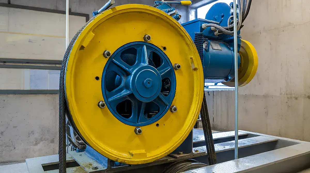
راهنمای انتخاب اینورتر آسانسور؛ از موتور گیربکس و گیرلس تا توان، جریان و تنظیمات درایو
انتخاب اینورتر آسانسور تنها به مطابقت توان موتور با عدد کیلووات روی درایو محدود نمیشود. دو موتور با توان یکسان، اگر از نظر ساختار، جریان نامی یا سیستم فیدبک متفاوت باشند، ممکن است به درایوها و روشهای کنترل متفاوتی نیاز داشته باشند. از طرف دیگر، مدلی که روی کاغذ با موتور سازگار است، باید در شرایط واقعی پروژه نیز از نظر ظرفیت اضافهبار، هماهنگی با تابلو فرمان و توالی ترمز تأیید شود.
برای شرکتهای آسانسوری و سازندگان تابلو، انتخاب درست یعنی کاهش ریسک ناسازگاری در نصب و راهاندازی، امکان پشتیبانی فنی روشن و تصمیم خرید مستند؛ مبنای این تصمیم، مشخصات دقیق موتور و سامانه است؛ نه صرفاً ظرفیت کابین، قیمت یا پیشنهاد یک مدل پرکاربرد.
در این راهنما، معیارهای اصلی انتخاب درایو برای موتورهای گیربکسی و گیرلس را مرور میکنیم، روش بررسی توان و جریان را با یک مثال مشخص نشان میدهیم و چند مدل سری L زیما را مقایسه میکنیم.
انتخاب درایو آسانسور از چه اطلاعاتی شروع میشود؟
پیش از استعلام قیمت یا بررسی موجودی مدلها، بهتر است یک شناسنامه کوتاه از پروژه تهیه شود. این کار بهویژه در پروژههای نوسازی و تعویض درایو اهمیت دارد؛ زیرا ممکن است بخشی از تجهیزات، از جمله موتور، انکودر یا تابلو فرمان، از قبل انتخاب شده باشند.
| اطلاعات موردنیاز | اهمیت آن در انتخاب درایو |
|---|---|
| نوع و پلاک موتور | تعیین سازگاری کنترل، توان، ولتاژ و جریان نامی |
| نوع انکودر و مدل دقیق آن | مشخصکردن نیاز به فیدبک و کارت PG سازگار |
| برق ورودی و مشخصات تابلو فرمان | بررسی ولتاژ، ورودیها، خروجیها و روش دریافت فرمان |
| سرعت نامی، ظرفیت، تردد و تعداد توقف | ارزیابی شرایط کاری و الزامات اضافهبار و حرارتی |
| سیستم ترمز و تجهیزات جانبی | بررسی هماهنگی با توالی ترمز و مدیریت انرژی برگشتی |
| الزامات نجات اضطراری | تعیین سازگاری درایو با معماری تابلو و برق پشتیبان |
نکته اجرایی: اگر قرار است درایو موجود جایگزین شود، کد کامل درایو قبلی، نسخه سختافزار یا نرمافزار و علت تعویض را نیز ثبت کنید. این دادهها برای بررسی قابلیت جایگزینی مستقیم یا نیاز به تغییر در طراحی تابلو ضروریاند.
درایو مناسب موتور گیربکسی و گیرلس چه تفاوتی دارد؟
تفاوت اصلی، فقط وجود یا نبود گیربکس نیست. نوع موتور و روش کنترل موردنیاز تعیین میکند چه خانوادهای از درایوها و چه تجهیزات جانبی باید بررسی شوند.
موتور آسنکرون گیربکسی؛ کنترل حلقه باز یا بسته
در بسیاری از آسانسورهای گیربکسی از موتور آسنکرون استفاده میشود. این موتورها بسته به طراحی تابلو و کیفیت کنترل موردنیاز، میتوانند با روش حلقه باز (Open Loop) یا حلقه بسته (Closed Loop) راهاندازی شوند.
در روش حلقه باز، درایو فیدبک مستقیم سرعت را از انکودر دریافت نمیکند. سادگی ساختار از مزایای این روش در کاربردهای سازگار است، اما رفتار سیستم در سرعت پایین، شروع حرکت و تغییر بار باید متناسب با الزامات پروژه ارزیابی شود.
در روش حلقه بسته، انکودر اطلاعات حرکت موتور را به درایو ارسال میکند. این فیدبک امکان کنترل دقیقتر را فراهم میکند؛ مشروط بر آنکه کارت PG، نوع سیگنال، تنظیمات و نسخه کنترلر با یکدیگر سازگار باشند.
موتور گیرلس؛ سازگاری با کنترل PM و انکودر
در بسیاری از سامانههای گیرلس، موتور از نوع سنکرون مغناطیس دائم (PM) است. در چنین پروژهای، انتخاب درایو باید علاوه بر توان و جریان، بر اساس پشتیبانی از روش کنترل موتور PM و نوع فیدبک موقعیت انجام شود.
در دفترچه رسمی سری L زیما، برای موتورهای گیرلس دارای انکودرهای EnDat و SinCos، کارتهای PG متناظر معرفی شدهاند. در نتیجه، وجود ورودی انکودر بهتنهایی معیار مناسبی برای اعلام سازگاری با یک موتور گیرلس نیست؛ کد دقیق انکودر و کارت مربوط باید تأیید شود.
جمعبندی انتخاب روش کنترل
| ترکیب موتور و فیدبک | روش کنترل در مستندات سری L | معیار تعیینکننده |
|---|---|---|
| موتور آسنکرون بدون انکودر | OLV / حلقه باز | تناسب عملکرد با نیاز حرکتی پروژه |
| موتور آسنکرون با انکودر افزایشی | CLV / حلقه بسته | سازگاری سیگنال و ولتاژ انکودر با PG |
| موتور گیرلس PM با EnDat | PM/CLV | کنترل PM و کارت EnDat-PG سازگار |
| موتور گیرلس PM با SinCos | PM/CLV | کنترل PM و کارت SinCos-PG سازگار |
این تمایز در انتخاب خانواده محصول نیز اهمیت دارد. مطابق بروشور رسمی زیما، L100 برای کنترل حلقه باز موتورهای آسنکرون معرفی شده و L200 امکانات کنترل حلقه باز و بسته برای کاربردهای مشخص آسنکرون و سنکرون را ارائه میکند. قابلیت نهایی باید با کد کامل مدل، کارت جانبی و نسخه دستگاه تطبیق داده شود؛ نمیتوان مشخصات یک خانواده را به همه مدلهای سری L تعمیم داد.
محاسبه توان و جریان درایو آسانسور؛ معیار تصمیم چیست؟
در پروژههایی که موتور از قبل مشخص است، معمولاً سؤال اصلی «محاسبه توان موتور» نیست؛ انتخاب درایوی است که بتواند موتور موجود را در شرایط کاری آسانسور بهدرستی کنترل کند. در این حالت، پلاک موتور مرجع اولیه است.
چرا بررسی آمپر در کنار کیلووات ضروری است؟
توان نامی موتور و توان درجشده در کاتالوگ درایو، انتخاب اولیه را محدود میکنند؛ اما جریان خروجی نامی درایو باید با جریان موتور و الزامات کارکرد آن سازگار باشد. همچنین باید ظرفیت اضافهبار، مدت مجاز تحمل آن و شرایط کاهش ظرفیت در دما یا ارتفاع متفاوت بررسی شود.
در این مرحله، جریان خروجی درایو اهمیت دارد؛ جریان ورودی درجشده در جدول محصول، جایگزین آن نیست.
نمونه بررسی یک موتور ۷٫۵ کیلوواتی
موتور زیر را بهعنوان یک مثال فرضی آموزشی در نظر بگیرید:
| مشخصه | مقدار |
|---|---|
| نوع موتور | آسنکرون گیربکسی |
| توان نامی | ۷٫۵ کیلووات |
| ولتاژ نامی | ۳۸۰ ولت سهفاز |
| جریان نامی | ۱۷ آمپر |
| انکودر | ندارد |
در جدول رسمی زیما، مدل L200C075-3 با توان ۷٫۵ کیلووات و جریان خروجی نامی ۱۹ آمپر معرفی شده است. بنابراین این مدل از نظر تطبیق اولیه توان، جریان و ولتاژ، یکی از گزینههایی است که میتوان بررسی کرد.
اما ۱۹ آمپر بودن خروجی بهتنهایی تأیید نهایی نیست. پیش از انتخاب باید مشخص شود:
- روش کنترل دستگاه برای موتور و تابلو موجود مناسب است؛
- جریان اضافهبار مجاز و مدت تحمل آن پاسخگوی سیکل کاری پروژه است؛
- محدودیتهای حرارتی و شرایط نصب رعایت میشوند؛
- توالی ترمز، فرمانهای تابلو و الزامات نجات اضطراری قابل پیادهسازیاند.
این مثال نشان میدهد چرا انتخاب درایو بر اساس «همکیلووات بودن» میتواند به نتیجه ناقص منجر شود.
اگر موتور هنوز انتخاب نشده باشد چه میشود؟
در طراحی یک آسانسور جدید، تعیین توان موتور مرحلهای مستقل است. محاسبات مکانیکی باید بار کابین و وزنه تعادل، سرعت، شتاب، نسبت تعلیق و راندمان اجزا را در نظر بگیرند. پس از محاسبه گشتاور موردنیاز، توان مکانیکی محور را میتوان از رابطه زیر به دست آورد:
توان مکانیکی (kW) = گشتاور محور (N.m) × سرعت (rpm) ÷ ۹۵۵۰
برای مثال، گشتاور ۷۱٫۶ نیوتنمتر در سرعت ۱۰۰۰ دور بر دقیقه، حدود ۷٫۵ کیلووات توان مکانیکی ایجاد میکند. این صرفاً یک تبدیل توان از گشتاور و سرعت است؛ نه فرمول کامل طراحی موتور آسانسور.
پس از تعیین موتور، انتخاب درایو همچنان به جریان، توانایی کنترل گشتاور، ظرفیت اضافهبار و سایر الزامات سیستم بستگی دارد.
آیا درایو باید همیشه یک رده توان بالاتر انتخاب شود؟
خیر. افزایش توان درایو فقط زمانی توجیه دارد که محاسبات بار، شرایط اضافهبار، محدودیتهای محیطی یا توصیه فنی سازنده آن را ایجاب کنند. انتخاب یک رده بالاتر بدون بررسی جریان و ویژگیهای کنترل، لزوماً ارزش فنی یا اقتصادی بیشتری ایجاد نمیکند.
مقایسه مدلهای منتخب درایو آسانسور زیما، سری L
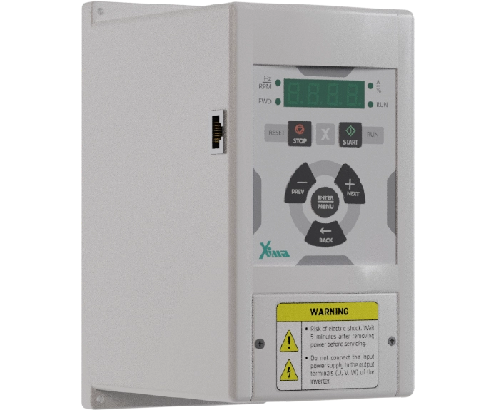
خانواده L زیما برای کاربردهای آسانسور و بالابر ارائه شده است. جدول زیر چند مدل را بر اساس توان و جریان خروجی اعلامشده در مشخصات رسمی محصول نشان میدهد.
| مدل | توان نامی | جریان خروجی نامی | برق ورودی |
|---|---|---|---|
| L100B055-3 | ۵٫۵ کیلووات | ۱۳ آمپر | سهفاز ۳۸۰ ولت |
| L200C075-3 | ۷٫۵ کیلووات | ۱۹ آمپر | سهفاز ۳۸۰ ولت |
| L200C110-3 | ۱۱ کیلووات | ۲۶ آمپر | سهفاز ۳۸۰ ولت |
| L200C150-3 | ۱۵ کیلووات | ۳۶ آمپر | سهفاز ۳۸۰ ولت |
نحوه استفاده از جدول: ابتدا ظرفیت جریان و ولتاژ را غربال کنید. سپس خانواده کنترل، نوع موتور، کارت PG موردنیاز و شرایط اضافهبار را در مستندات همان مدل بررسی کنید. جدول فوق برای مقایسه اولیه است و نباید بهعنوان پیشنهاد قطعی خرید برای موتورهای گیربکسی یا گیرلس استفاده شود.
مدلهای L300 نیز در فهرست رسمی سری L وجود دارند، اما ویژگیها و الزامات آنها باید بر اساس مستندات بهروز همان مدل تأیید شود.
مشخصات کاملتر در صفحه معرفی سری L زیما و بخش محصولات آسانسور و بالابر قابل بررسی است.
سازگاری با تابلو فرمان و شرایط راهاندازی؛ بخش مهم انتخاب درایو
در پروژههای آسانسوری، انتخاب درایو بدون بررسی ارتباط آن با تابلو فرمان و تجهیزات جانبی کامل نیست. این موضوع در جایگزینی درایو موجود اهمیت بیشتری دارد؛ زیرا ممکن است موتور و بخش عمدهای از تابلو بدون تغییر باقی بمانند.
اطلاعات موتور و روش کنترل
پارامترهای موتور باید بر اساس پلاک و راهنمای نسخه دقیق درایو تنظیم شوند. دفترچه سری L زیما برای مشخصاتی مانند جریان، ولتاژ، توان و سرعت موتور فیلدهای مشخصی در نظر گرفته است. اختلاف اطلاعات واقعی موتور با مقادیر تنظیمشده میتواند بر کیفیت کنترل و عملکرد حفاظتی اثر بگذارد.
انکودر و کارت PG
در سیستمهای حلقه بسته، سازگاری نوع سیگنال انکودر، ولتاژ و کارت PG باید پیش از راهاندازی روشن باشد. در راهنمای سری L، کارتهای 5i-PG، 12i-PG، EnDat-PG و SinCos-PG برای کاربردهای متفاوت معرفی شدهاند. بنابراین صرف یکسان بودن کانکتور یا نام کلی «انکودر» برای تأیید سازگاری کافی نیست.
AutoTune و کیفیت حرکت
شناسایی مشخصات موتور یا AutoTune، تنظیمات شتاب و کاهش سرعت و هماهنگی فرمانها بر عملکرد نهایی اثر میگذارند. بااینحال، روش اجرای این مراحل به نوع موتور، فیدبک و شرایط نصب بستگی دارد. بهویژه در موتورهای گیرلس، راهاندازی باید طبق مستندات نسخه مربوط و توسط متخصص واجد صلاحیت انجام شود.
توالی ترمز و سیستم نجات
درایو بخشی از سامانه کنترل حرکت است؛ جایگزین ترمز مکانیکی یا مدارهای ایمنی نیست. توالی فرمان ترمز، وضعیت کنتاکتورها، فیدبکها و منطق تابلو باید در طراحی و آزمون سیستم بررسی شوند.
دفترچه سری L همچنین بخشی را به حالت نجات اضطراری (Rescue) اختصاص داده است. استفاده از این قابلیت در یک پروژه مشخص، نیازمند تأیید سازگاری درایو با معماری تابلو، منبع برق پشتیبان و الزامات ایمنی سیستم است.
مقاومت ترمز و مدیریت انرژی برگشتی در آسانسور
در آسانسور کششی، بسته به جهت حرکت و اختلاف وزن کابین و وزنه تعادل، موتور ممکن است در بخشی از سیکل حرکت وارد وضعیت باززاینده شود. در این شرایط، انرژی به مدار الکتریکی درایو بازمیگردد.
اگر ظرفیت مدیریت این انرژی متناسب با پروژه نباشد، احتمال افزایش ولتاژ باس DC و بروز خطای اضافهولتاژ وجود دارد. ازاینرو مقاومت ترمز، مقدار مقاومت، توان حرارتی و سیکل کاری آن باید طبق مشخصات مدل و شرایط واقعی آسانسور تعیین شوند.
برای عیبیابی خطاهای مرتبط، ثبت کد خطا همراه با جهت حرکت، وضعیت بار، مرحله وقوع و مدل دقیق درایو ضروری است. راهنمای خطاهای درایو زیما برای طبقهبندی اولیه خطاها قابل استفاده است؛ تشخیص علت و اصلاح مدار باید تخصصی انجام شود.
در خرید B2B درایو آسانسور، علاوه بر مشخصات فنی چه عواملی مهماند؟
در خرید پروژهای، پایینترین قیمت اولیه لزوماً به معنی کمترین هزینه تمامشده نیست. هزینههای احتمالی تغییر تابلو، زمان راهاندازی، دسترسی به مستندات، قطعات جانبی و خدمات فنی نیز بخشی از تصمیم تأمین تجهیزاتاند.
برای ارزیابی گزینهها، این موارد را در کنار توان و جریان قرار دهید:
- سازگاری با تجهیزات موجود: آیا تغییر کارت، سیمبندی یا منطق فرمان لازم است؟
- شفافیت مستندات: آیا دفترچه نسخهدار، اطلاعات مدل و مشخصات پارامترها در دسترس است؟
- نیاز به تجهیزات جانبی: کارت PG، مقاومت ترمز یا ملزومات دیگر در برآورد دیده شدهاند؟
- پشتیبانی فنی: مسیر دریافت مشاوره برای انتخاب مدل، راهاندازی و عیبیابی مشخص است؟
- تداوم تأمین و نگهداری: وضعیت دسترسی به مدل جایگزین و قطعات موردنیاز پروژه چگونه است؟
این معیارها بهویژه برای شرکتهایی اهمیت دارند که چند پروژه را بهصورت همزمان اجرا میکنند یا مسئولیت خدمات پس از نصب را بر عهده دارند.
خطاهای متداول در انتخاب و سفارش درایو آسانسور
| خطای تصمیمگیری | پیامد احتمالی | رویکرد مناسب |
|---|---|---|
| انتخاب فقط از روی ظرفیت کابین | نادیدهماندن ویژگی موتور و سیستم | استفاده از پلاک و مشخصات واقعی پروژه |
| تطبیق صرفاً بر اساس کیلووات | انتخاب نامتناسب با جریان یا اضافهبار | بررسی جریان خروجی و شرایط کاری |
| یکسان دانستن گیربکس و گیرلس | ناسازگاری روش کنترل یا فیدبک | تعیین نوع موتور و انکودر پیش از استعلام |
| فرض سازگاری همه کارتهای PG | خطای فیدبک یا نیاز به تغییر تجهیز | تطبیق مدل انکودر و کارت با مستندات |
| تعمیم مشخصات یک مدل به کل سری | انتخاب بر مبنای قابلیت تأییدنشده | بررسی کد کامل مدل و نسخه دستگاه |
| نادیدهگرفتن تابلو و ترمز | افزایش ریسک تغییرات حین اجرا | بازبینی ارتباطات و توالی عملکرد پیش از خرید |
چکلیست استعلام فنی درایو آسانسور
برای دریافت پیشنهاد مدل دقیقتر و قابل مقایسه، بهتر است استعلام شامل این اطلاعات باشد:
- مشخصات پروژه: ظرفیت، سرعت نامی، کاربری و میزان تردد؛
- موتور: برند و مدل، نوع گیربکس/گیرلس، توان، ولتاژ، جریان و دور نامی؛
- فیدبک: نوع و مدل کامل انکودر و کارت موجود؛
- تابلو فرمان: برند/مدل، نوع فرماندهی و ورودی/خروجیهای موردنیاز؛
- برق و شرایط نصب: ولتاژ ورودی، وضعیت تابلو و شرایط محیطی؛
- تجهیزات جانبی: مشخصات ترمز، مقاومت ترمز و سیستم نجات؛
- در پروژه تعویض: مدل و نسخه درایو قبلی، دلیل جایگزینی و خطاهای ثبتشده.
با این اطلاعات، امکان بررسی سازگاری و مقایسه مدلهای پیشنهادی بسیار دقیقتر از استعلامی است که فقط «درایو آسانسور ۷٫۵ کیلووات» را ذکر میکند.
پرسشهای متداول درباره انتخاب اینورتر آسانسور
آیا میتوان مدل درایو را فقط با توجه به ظرفیت کابین مشخص کرد؟
خیر. ظرفیت کابین یکی از ورودیهای طراحی است، اما برای انتخاب درایو باید مشخصات موتور، جریان نامی، نوع کنترل، انکودر و شرایط تابلو نیز در دسترس باشند.
آیا یک درایو حلقه باز برای موتور گیرلس مناسب است؟
صرف پشتیبانی از کنترل حلقه باز، تأییدکننده سازگاری با موتور گیرلس PM نیست. دستگاه باید از نوع موتور و روش کنترل موردنیاز پشتیبانی کند و با انکودر و کارت PG مربوط سازگار باشد.
آیا انتخاب درایو با توان بالاتر همیشه مطمئنتر است؟
خیر. سایزبندی باید بر اساس جریان موتور، ظرفیت اضافهبار، سیکل کاری و شرایط حرارتی انجام شود. انتخاب یک مدل بزرگتر بدون مبنای فنی، لزوماً مسئله سازگاری کنترل را حل نمیکند.
برای جایگزینی درایو موجود، چه اطلاعاتی لازم است؟
علاوه بر پلاک موتور و مشخصات انکودر، کد و نسخه درایو قبلی، نقشه تابلو فرمان، تجهیزات جانبی و علت تعویض اهمیت دارند. هدف این است که نیاز احتمالی به تغییرات تابلو پیش از سفارش روشن شود.
آیا درایو سری L زیما از حالت نجات اضطراری پشتیبانی میکند؟
حالت Rescue در مستندات سری L شرح داده شده است. قابلیت و نحوه استفاده در هر پروژه باید بر اساس کد و نسخه مدل، تابلو فرمان، منبع برق پشتیبان و طراحی سیستم تأیید شود.
چرا هنگام کاهش سرعت، خطای اضافهولتاژ رخ میدهد؟
یکی از علتهای احتمالی، برگشت انرژی به مدار درایو است. بااینحال، تشخیص دقیق به بررسی کد خطا، شرایط بار، روش توقف، برق ورودی و تجهیزات مدیریت انرژی نیاز دارد.
جمعبندی؛ انتخاب فنی مستند، مبنای یک خرید قابل دفاع
برای انتخاب اینورتر آسانسور، معیار اصلی فقط توان نامی نیست. نوع موتور، جریان پلاک، روش کنترل، انکودر، ظرفیت اضافهبار، سازگاری با تابلو فرمان و الزامات ترمز باید در کنار یکدیگر بررسی شوند. تفاوت موتورهای گیربکسی و گیرلس نیز باعث میشود یک پیشنهاد یکسان برای همه پروژهها قابل اتکا نباشد.
خانواده درایوهای سری L زیما مدلهای متنوعی برای بررسی دارد. انتخاب نهایی زمانی قابل دفاع است که کد مدل، ظرفیت جریان و قابلیتهای کنترل آن با مشخصات واقعی پروژه و مستندات فنی سازگار باشند.
برای استعلام فنی و بررسی مدل مناسب، اطلاعات موتور، انکودر و تابلو فرمان را آماده کنید و از طریق صفحه ارتباط با زیما درخواست بررسی ثبت کنید.
Selecting an elevator inverter involves considerably more than matching the motor’s kilowatt rating to the number on a drive. Two motors with the same rated power may require different drives and control strategies if their construction, rated current or feedback systems differ. Even when a drive appears compatible on paper, its overload capability, interface with the elevator controller and brake sequencing must be verified against the actual operating conditions.
For elevator contractors and control panel manufacturers, the objective is clear: minimise integration and commissioning risks, secure reliable technical support and make a purchasing decision backed by engineering data. That decision should be based on the motor and system specifications—not cabin capacity, unit price or the popularity of a particular model alone.
This guide covers the principal selection criteria for geared and gearless elevator motors, explains how to assess power and current with a practical example, and compares selected XIMA L-Series elevator drives using published technical specifications.
What Information Do You Need Before Selecting an Elevator Drive?
Before requesting a quotation or checking model availability, compile a concise technical profile of the installation. This is particularly important for modernisation and drive replacement projects, where the motor, encoder and elevator control panel may already be fixed.
- Motor type and nameplate: Establish the required control compatibility, rated power, voltage and motor current.
- Encoder type and exact model: Identify the feedback requirements and the compatible PG interface card.
- Power supply and elevator controller: Confirm supply compatibility, I/O requirements and command interfaces.
- Rated speed, capacity, traffic and number of stops: Assess the duty cycle, overload requirements and thermal operating conditions.
- Mechanical brake and auxiliary equipment: Review brake sequencing and regenerative-energy management requirements.
- Emergency rescue requirements: Confirm compatibility with the control panel architecture and backup power system.
For replacement projects: Record the full model code of the existing drive, its hardware or firmware version and the reason for replacement. This information helps determine whether a direct replacement is possible or changes to the control panel will be necessary.
Geared vs Gearless Elevator Motors: What Changes in Drive Selection?
The key distinction is not simply whether a gearbox is present. Motor technology and the required control method determine which drive family, feedback interface and auxiliary components should be considered.
Geared Induction Motors: Open-Loop or Closed-Loop Control
Many geared elevator systems use asynchronous, or induction, motors. Depending on the control panel design and motion-performance requirements, these motors may operate with open-loop or closed-loop control.
With open-loop control, the inverter does not receive direct motor-speed feedback from an encoder. The simpler hardware architecture can be an advantage in suitable applications. However, low-speed behaviour, starting performance and response to load changes must still meet the project’s motion-control requirements.
With closed-loop control, an encoder feeds motor-motion information back to the drive. This enables more precise control, provided that the encoder signal, PG card, parameter settings and controller version are compatible.
Gearless Motors: PM Motor Control and Encoder Compatibility
Many gearless elevator systems use permanent-magnet synchronous motors (PMSMs). In these applications, matching the drive’s power and current ratings is only part of the selection process. The drive must also support the required PM motor control method and rotor-position feedback.
XIMA’s L-Series technical documentation identifies dedicated PG interfaces for gearless motors equipped with EnDat or SinCos encoders.
Therefore, an encoder input on the drive does not, by itself, establish compatibility with a particular gearless motor. The encoder’s exact model, electrical characteristics and corresponding PG card must be confirmed.
The applicable documentation can be located through the XIMA English technical downloads page.
Control-Method Selection at a Glance
- Induction motor without an encoder — OLV (open-loop vector control): Verify that the expected motion performance satisfies the project requirements.
- Induction motor with an incremental encoder — CLV (closed-loop vector control): Confirm that the encoder signal and supply voltage are compatible with the PG card.
- Gearless PM motor with an EnDat encoder — PM/closed-loop control: Verify PM motor control support and compatibility with the appropriate EnDat-PG card.
- Gearless PM motor with a SinCos encoder — PM/closed-loop control: Verify PM motor control support and compatibility with the appropriate SinCos-PG card.
This distinction also affects product-family selection.
XIMA presents the L100 family for open-loop control of induction motors, while the L200 family offers a broader range of open-loop and closed-loop control functions for specified induction and synchronous motor applications.
Final compatibility must be checked against the complete drive model code, installed option cards and hardware/software revision. A capability listed for one family or variant should never be assumed to apply to every L-Series model.
How to Size an Elevator Inverter: Power, Current and Operating Conditions
When the motor has already been selected, the task is generally not to recalculate motor power from scratch. It is to select a drive capable of controlling that motor throughout the elevator’s real operating cycle.
The motor nameplate provides the starting point.
Why Rated Output Current Matters as Much as Kilowatts
Motor power and the drive’s published kW rating help narrow down the options. However, the drive’s rated output current must be compatible with the motor’s rated current and operating requirements.
The drive’s overload rating, permitted overload duration and any derating caused by ambient temperature or installation altitude must also be assessed.
At this stage, compare the motor current with the drive’s output current. The input-current value in a product table is not a substitute.
Worked Example: A 7.5 kW Geared Elevator Motor
Consider the following illustrative, hypothetical motor:
- Motor type: Geared induction motor
- Rated power: 7.5 kW
- Rated voltage: 380 V, three-phase
- Rated current: 17 A
- Encoder: None
According to XIMA’s published product specifications, the L200C075-3 is rated at 7.5 kW with a 19 A rated output current.
On the basis of power, voltage and initial current comparison, it is therefore a candidate worth evaluating.
Refer to the XIMA L-Series elevator and lift drive range for the published model information.
A 19 A drive rating is not, however, a final application approval. The project engineer must still verify that:
- The drive’s control method is appropriate for the motor and existing controller.
- The allowable overload current and duration cover the installation’s duty cycle.
- Thermal limits and installation conditions are respected.
- Brake sequencing, control-panel commands and emergency rescue requirements can be implemented correctly.
The example illustrates why selecting an elevator drive solely because its kW rating matches the motor can be insufficient.
What If the Elevator Motor Has Not Yet Been Selected?
For a new elevator installation, motor sizing is a separate engineering exercise.
Mechanical calculations must account for car and counterweight loads, rated speed, acceleration, suspension ratio and the efficiency of the system’s components.
Once the required shaft torque is known, mechanical shaft power can be calculated using:
Mechanical power (kW) = Shaft torque (N·m) × Rotational speed (rpm) ÷ 9,550
For example, 71.6 N·m at 1,000 rpm corresponds to approximately 7.5 kW of mechanical power.
This is a conversion between torque, speed and power—not a complete formula for sizing an elevator motor.
After the motor is selected, the inverter must still be assessed for rated current, torque-control capability, overload capacity and the remaining system requirements.
Should You Always Choose the Next Drive Size Up?
No. Upsizing is justified when load calculations, overload demands, environmental derating or the manufacturer’s application guidance make it necessary.
Choosing a larger drive without examining current and control capability does not automatically provide a technical or commercial advantage.
Selected XIMA L-Series Elevator Drives Compared
XIMA’s L Series is designed for elevator and lift applications.
The following model-by-model overview uses the rated power and output current stated in the published product specifications.
- L100B055-3: Rated power 5.5 kW; rated output current 13 A; supply 380 V, three-phase.
- L200C075-3: Rated power 7.5 kW; rated output current 19 A; supply 380 V, three-phase.
- L200C110-3: Rated power 11 kW; rated output current 26 A; supply 380 V, three-phase.
- L200C150-3: Rated power 15 kW; rated output current 36 A; supply 380 V, three-phase.
How to use this comparison: First, screen the options for suitable current and voltage ratings.
Next, verify the control family, motor type, required PG card and overload characteristics in the documentation for the exact model.
This list supports preliminary comparison; it is not a final purchase recommendation for either a geared or gearless installation.
L300 models also appear in XIMA’s L-Series product range, but their features and application requirements must be checked against the latest documentation for the relevant variant.
For model-level information, see the English XIMA L-Series elevator and lift product category.
Control Panel Compatibility and Commissioning Requirements
Drive selection is incomplete until its interfaces with the elevator controller and auxiliary equipment have been reviewed.
This is especially important in drive replacement projects, where the motor and much of the control panel may remain unchanged.
Motor Data and Control Parameters
Motor parameters must be entered in accordance with the nameplate and the operating manual for the specific drive revision.
The L-Series documentation provides settings for data such as motor current, voltage, power and speed.
Differences between the actual motor characteristics and the configured values can affect motion performance and protective functions.
Encoder Signals and PG Cards
For closed-loop systems, confirm the encoder signal type, supply voltage and interface-card compatibility before commissioning.
L-Series documentation describes 5i-PG, 12i-PG, EnDat-PG and SinCos-PG cards for different feedback applications.
A matching connector—or the generic description encoder compatible—does not establish that a particular encoder will function correctly with a particular drive.
Auto-Tuning and Ride Quality
Motor identification or AutoTune, acceleration and deceleration settings, and command coordination all influence final ride performance.
The correct commissioning procedure depends on motor technology, feedback configuration and installation conditions.
Gearless PM systems in particular require the applicable revision-specific instructions and a qualified commissioning engineer.
Mechanical Brake Sequencing and Emergency Rescue
The inverter is part of the motion-control system; it does not replace the mechanical brake or the elevator’s safety circuits.
Brake command timing, contactor states, feedback signals and the control panel’s operating logic must be validated during system design and testing.
The L-Series documentation also describes an emergency Rescue operating mode.
Whether and how this function can be used in a specific installation depends on the drive model and revision, controller architecture, backup power source and the overall safety design.
For parameter definitions and commissioning prerequisites, consult the applicable L-Series manual through XIMA’s English downloads centre.
Changes affecting elevator motion or safety must be handled by qualified personnel under the project’s approved commissioning procedure.
Braking Resistors and Regenerative Energy in Elevator Systems
In a traction elevator, the motor can operate regeneratively during part of the travel cycle, depending on travel direction and the load difference between the car and counterweight.
Under these conditions, energy flows back toward the drive’s electrical circuit.
If the energy-handling arrangement is not properly matched to the application, the DC bus voltage can rise and trigger an overvoltage fault.
Braking-resistor resistance, power/thermal rating and duty-cycle capability must therefore be selected according to the exact drive specifications and elevator operating profile.
When investigating related faults, record the complete fault code together with travel direction, car load, the point in the motion cycle at which the fault occurred and the exact drive model.
The English guide to XIMA drive error codes can assist with initial fault classification; diagnosis and corrective electrical work require qualified technical personnel.
B2B Elevator Drive Procurement: Consider More Than the Unit Price
For project procurement, the lowest initial price does not necessarily represent the lowest installed cost.
Control panel modifications, commissioning time, access to documentation, additional components and technical support all affect the commercial outcome.
Alongside power and current ratings, evaluate the following:
- Compatibility with installed equipment: Will a different interface card, wiring arrangement or command sequence be needed?
- Documentation quality: Are revision-controlled manuals, model data and parameter descriptions available?
- Accessories: Have PG cards, braking resistors and other required components been included in the scope and quotation?
- Technical support: Is there a clear process for model selection, commissioning assistance and troubleshooting?
- Continuity of supply and maintenance: Can the project obtain a suitable replacement model and the spare components required for service?
These factors are particularly relevant to elevator companies delivering multiple projects simultaneously or assuming long-term responsibility for after-installation maintenance.
Common Mistakes When Specifying an Elevator Inverter
- Selecting the drive from cabin capacity alone: This can overlook critical motor and system requirements. Base the selection on motor-nameplate data and actual project specifications.
- Matching only the kW rating: The drive may not provide sufficient output current or overload capability. Check rated output current, duty requirements and applicable derating.
- Treating geared and gearless systems alike: This can result in incompatible control methods or feedback interfaces. Identify the motor technology and encoder type before requesting a quotation.
- Assuming all PG cards are interchangeable: An incorrect interface may produce feedback faults or require hardware changes. Match the exact encoder and PG card to the manufacturer’s documentation.
- Applying one model’s features to an entire drive series: This risks purchasing equipment based on capabilities that have not been confirmed. Verify the complete model code and device revision.
- Overlooking the controller and brake sequence: Missing these requirements can lead to unplanned changes during installation. Review the electrical interfaces and operating sequence before procurement.
Elevator Drive RFQ Checklist: What to Send Your Supplier
For a precise and comparable technical quotation, include the following information in the request for quotation (RFQ):
- Project: Rated car capacity, speed, application and expected traffic or duty cycle.
- Motor: Manufacturer and model, geared or gearless design, power, voltage, rated current and rated speed.
- Feedback: Full encoder type and model, plus any existing interface card.
- Elevator controller: Manufacturer and model, command method and required input/output signals.
- Power and installation: Supply voltage, panel conditions and operating environment.
- Accessories: Mechanical-brake details, braking resistor and emergency rescue configuration.
- For replacements: Existing drive model and revision, reason for replacement and recorded fault history.
An RFQ containing these details enables a much more reliable compatibility assessment than a request that says only 7.5 kW elevator inverter.
Frequently Asked Questions About Elevator Inverter Selection
Can I select an elevator inverter based on cabin capacity alone?
No. Cabin capacity is an input to elevator design, but drive selection also requires motor specifications, rated current, control method, encoder details and control panel requirements.
Is an open-loop drive suitable for a gearless elevator motor?
Open-loop capability alone does not confirm compatibility with a gearless PM motor.
The inverter must support the required motor technology and control method, as well as the relevant encoder and PG interface.
Is a higher-power inverter always the safer choice?
No. Sizing should be based on rated motor current, overload capability, duty cycle and thermal operating conditions.
A larger drive does not necessarily solve a control-compatibility issue.
What information is required when replacing an existing elevator drive?
In addition to the motor nameplate and encoder specifications, provide the previous drive’s complete model and revision, controller wiring diagrams, relevant accessories and reason for replacement.
This helps identify any necessary panel changes before an order is placed.
Does the XIMA L Series support emergency rescue operation?
The L-Series technical documentation describes a Rescue function.
Its availability and implementation for an individual project must be verified against the exact model and revision, elevator controller, backup power supply and system design.
Why does an overvoltage fault occur during elevator deceleration?
Regenerative energy returning to the drive is one possible cause.
A reliable diagnosis also requires the recorded fault code, load conditions, stopping profile, incoming supply and braking-energy management equipment.
Conclusion: Make Elevator Drive Selection an Evidence-Based Engineering Decision
Choosing the right elevator inverter takes more than a nominal power match.
Motor technology, nameplate current, control method, encoder compatibility, overload capability, controller integration and brake requirements must be considered together.
Differences between geared and gearless elevators mean that a single drive recommendation cannot be applied indiscriminately across projects.
The XIMA L-Series drive range provides several models for evaluation.
A final selection is defensible only when the exact model’s current rating and control capabilities have been checked against the installation’s technical requirements and the manufacturer’s documentation.
To request a project-specific technical review and drive recommendation, prepare the motor, encoder and elevator controller information, then consult the XIMA L-Series elevator and lift product range.
محصولات
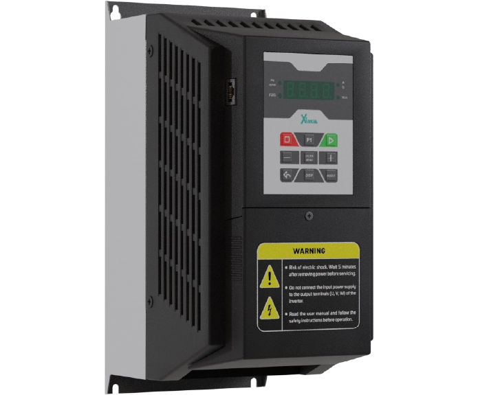
اینورتر 15 کیلووات سه فاز سری بالابر و جرثقیل
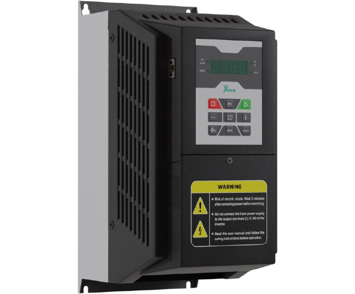
اینورتر 11 کیلووات سه فاز سری بالابر و جرثقیل
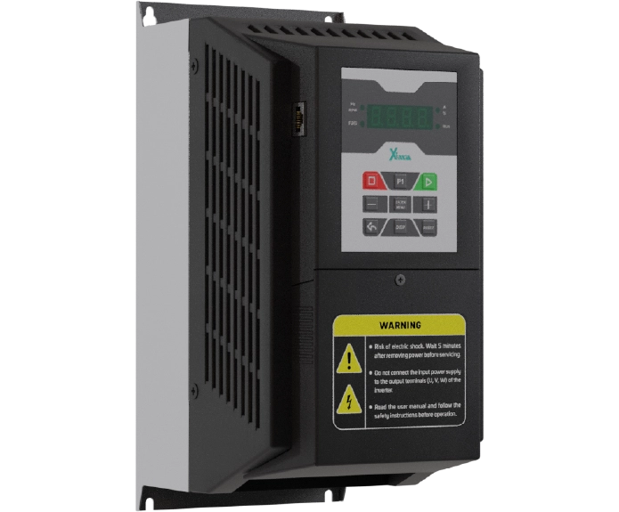
اینورتر 7.5 کیلووات سه فاز سری بالابر و جرثقیل
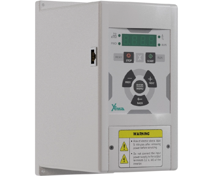
اینورتر 5.5 کیلووات سه فاز سری بالابر و جرثقیل
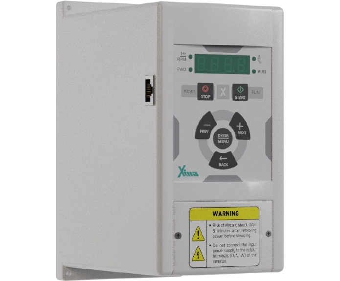
اینورتر 4 کیلووات سه فاز سری بالابر و جرثقیل
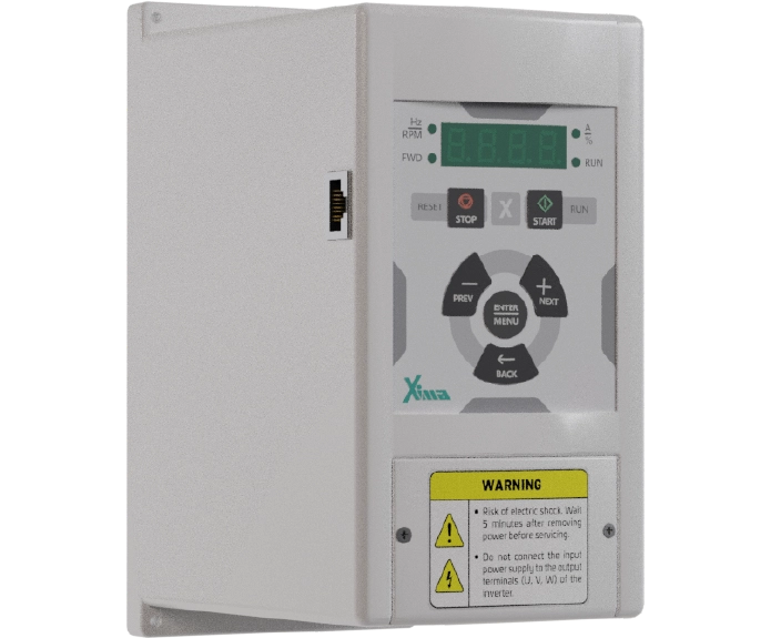
اینورتر 3 کیلووات سه فاز سری بالابر و جرثقیل
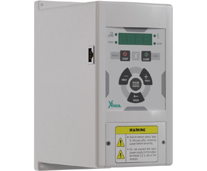
اینورتر 2.2 کیلووات سه فاز سری بالابر و جرثقیل
نظرات کاربران
دیدگاهها
هنوز دیدگاهی ثبت نشده است.