علت لرزش آسانسور چیست؟ بررسی ۹ علت فنی و روش عیبیابی

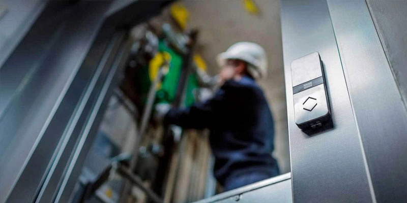
علت لرزش و ضربه زدن آسانسور؛ از استارت تا توقف
علت لرزش آسانسور همیشه خرابی موتور یا درایو نیست. تنظیم نبودن ریل و کفشک، اختلال در عملکرد ترمز، ناهماهنگی گشتاور موتور، مشکلات انکودر و تنظیمات نامناسب شتاب و سرعت، همگی میتوانند باعث لرزش یا ضربه در کابین شوند. برای تشخیص درست، ابتدا باید مشخص شود لرزش هنگام شروع حرکت، شتابگیری، حرکت با سرعت ثابت یا توقف اتفاق میافتد.
برای مثال، ضربهای که فقط در لحظه استارت احساس میشود، ممکن است به هماهنگی ترمز و گشتاور موتور مربوط باشد؛ اما لرزشی که در یک ارتفاع مشخص از چاه تکرار میشود، احتمال وجود مشکل در ریلها، کفشکها یا اتصالات مکانیکی را بیشتر میکند.
در این راهنما، دلایل لرزش کابین آسانسور را از دیدگاه مکانیکی و کنترلی بررسی میکنیم و روش تشخیص ایرادهای مرتبط با حرکت موتور، انکودر و ترمز را توضیح میدهیم.
فهرست مطالب
نکته ایمنی: اگر آسانسور دچار لرزش شدید، ضربه غیرعادی، عقبگرد ناخواسته یا اختلال در توقف شده است، تا بررسی و تأیید ایمنی توسط تکنسین واجد صلاحیت نباید به سرویس عادی بازگردد. اطلاعات این مقاله برای شناخت و عیبیابی تخصصی است و مجوز تغییر آزمایشی تنظیمات ترمز یا تجهیزات ایمنی محسوب نمیشود.
علت لرزش آسانسور در یک نگاه؛ از کجا عیبیابی را شروع کنیم؟
قبل از بازکردن تجهیزات یا تغییر پارامترهای درایو، زمان و شرایط وقوع لرزش را بررسی کنید. این اطلاعات، محدوده احتمالی مشکل را کوچکتر میکند.
| زمان یا نوع لرزش | علت احتمالی | اولویت بررسی |
|---|---|---|
| ضربه در لحظه شروع حرکت | ناهماهنگی ترمز و گشتاور، تنظیمات شتاب | سیستم ترمز و فرمان حرکت |
| لرزش هنگام شتابگیری | تنظیم نامناسب Jerk، اطلاعات موتور، مشکلات مکانیکی | پروفیل حرکت و مجموعه محرکه |
| لرزش در سرعت ثابت | ریل، کفشک، بلبرینگ، فلکه یا نوسان سرعت موتور | تجهیزات مکانیکی و فیدبک |
| لرزش در سرعت پایین | کنترل موتور، انکودر یا اصطکاک مکانیکی | سیستم کنترل و وضعیت مکانیکی |
| ضربه هنگام نزدیکشدن به طبقه | کاهش سرعت یا تنظیمات تراز طبقه | Deceleration و Leveling |
| تکان پس از توقف | عملکرد ترمز و ترتیب قطع گشتاور | Brake Sequence |
| لرزش در یک محدوده مشخص چاه | ریل، اتصالات یا کفشکها | بازرسی مکانیکی همان محدوده |
| لرزش وابسته به میزان بار | سیستم تعلیق، گشتاور و ترمز | بررسی شرایط بار و تجهیزات محرکه |
این جدول برای تعیین مسیر عیبیابی است، نه تشخیص قطعی. ممکن است چند عامل مکانیکی و الکتریکی بهصورت همزمان باعث لرزش شوند.
مهمترین دلایل مکانیکی لرزش کابین آسانسور
در بسیاری از آسانسورها، ارتعاش از مجموعه مکانیکی ایجاد میشود و از طریق سیستم تعلیق یا تجهیزات راهنما به کابین انتقال پیدا میکند. در چنین وضعیتی، تغییر تنظیمات درایو بدون برطرفکردن منشأ مکانیکی، راهکار مناسبی نیست.
۱. تنظیم نبودن ریلهای راهنما
ریلهای راهنما مسیر حرکت کابین و وزنه تعادل را مشخص میکنند. مشکلات همراستایی ریلها، اتصالات، براکتها یا کیفیت سطح ریل میتواند باعث حرکت ناصاف کابین شود.
یکی از نشانههای مهم، تکرار لرزش در ارتفاع مشخصی از چاه است.
اگر کابین در بیشتر مسیر حرکت نرمی دارد، اما هنگام عبور از یک ناحیه خاص دچار تکان جانبی میشود، وضعیت ریل و اتصالات آن بخش باید بررسی شود.
البته این الگو بهتنهایی خرابی ریل را اثبات نمیکند؛ تجهیزات و فرمانهای وابسته به موقعیت کابین نیز ممکن است در رفتار سیستم نقش داشته باشند.
۲. خرابی یا فرسودگی کفشکهای راهنما
کفشکها وظیفه هدایت کابین و وزنه تعادل در امتداد ریل را بر عهده دارند. فرسودگی، لقی، تنظیم نبودن فاصله یا مشکل در عملکرد کفشکهای لغزشی و غلتکی میتواند ارتعاش جانبی ایجاد کند.
در سیستمهای دارای کفشک غلتکی، وضعیت غلتکها و یاتاقانهای آنها نیز اهمیت دارد.
نکته قابل توجه این است که منشأ لرزش همیشه در خود کابین قرار ندارد. بعضی مشکلات مجموعه راهنمای وزنه تعادل نیز میتوانند از طریق سیستم تعلیق به حرکت کابین منتقل شوند.
۳. مشکلات موتور، گیربکس، فلکه و بلبرینگ
فرسودگی بلبرینگ، ناهممحوری اجزای محرکه، لقی اتصالات یا نامتعادل بودن قطعات دوار میتواند لرزشی ایجاد کند که با سرعت حرکت تغییر میکند.
بهعنوان مثال، اگر شدت یا فرکانس ارتعاش با افزایش سرعت موتور تغییر کند، بررسی قطعات دوار و اتصالات مکانیکی اهمیت بیشتری پیدا میکند.
در آسانسورهای گیربکسدار، وضعیت گیربکس و کوپلینگهای مرتبط نیز باید ارزیابی شود. در سیستمهای گیرلس، بررسی مجموعه موتور و فلکه کششی اهمیت ویژهای دارد.
شنیدهشدن صدای مکانیکی همراه با لرزش میتواند نشانه تکمیلی باشد، اما برای تشخیص قطعه معیوب کافی نیست.
۴. کشش نامتعادل سیمبکسلها
در آسانسورهای کششی، اختلاف نامناسب در کشش سیمبکسلها میتواند بر رفتار سیستم تعلیق و مجموعه فلکهها اثر بگذارد.
در این شرایط، لازم است وضعیت سیمبکسلها، سربکسلها، فلکهها و تجهیزات مرتبط طبق دستورالعمل سازنده ارزیابی شود.
همچنین در آسانسورهایی که از زنجیر یا کابل جبران استفاده میکنند، وضعیت نصب، اتصالات و حرکت تجهیزات جبران نیز باید بررسی شود.
نکته تخصصی: اگر لرزش در جهت حرکت رو به بالا و پایین یکسان نیست یا با تغییر بار کابین شدت متفاوتی پیدا میکند، این تفاوت باید ثبت شود. الگوی وابسته به بار میتواند در بررسی تعادل، اصطکاک و کنترل گشتاور مفید باشد.
علت لرزش آسانسور هنگام شروع حرکت چیست؟
لرزش هنگام استارت معمولاً بهصورت تکان اولیه، ضربه کوتاه یا حرکت نامنظم در لحظه آغاز حرکت احساس میشود.
در آسانسورهای کششی مجهز به درایو کنترل سرعت، شروع حرکت به هماهنگی چند عامل وابسته است: تولید گشتاور کافی، آزادشدن ترمز مکانیکی و اجرای صحیح پروفیل شتاب.
ناهماهنگی ترمز مکانیکی و گشتاور موتور
پیش از شروع حرکت، موتور باید بتواند گشتاور لازم برای کنترل بار را فراهم کند. همزمان، فرمان آزادشدن ترمز باید مطابق توالی طراحیشده اجرا شود.
اگر ترمز پیش از ایجاد گشتاور کافی آزاد شود، ممکن است کابین برای لحظهای در جهت ناخواسته جابهجا شود.
در مقابل، اگر موتور شروع به تولید گشتاور کند اما ترمز هنوز کاملاً آزاد نشده باشد، ممکن است تنش مکانیکی، صدا یا ضربه ایجاد شود.
به همین دلیل، هنگام بررسی لرزش در استارت، باید عملکرد واقعی ترمز و زمانبندی فرمانهای درایو در کنار یکدیگر ارزیابی شوند.
نکتهای که گاهی در عیبیابی نادیده گرفته میشود: صدور فرمان الکتریکی آزادشدن ترمز، لزوماً به معنای آزادشدن آنی و کامل ترمز مکانیکی نیست. زمان پاسخ واقعی ترمز، وضعیت لنتها، سیمپیچ و مجموعه مکانیکی آن نیز بر کیفیت شروع حرکت تأثیر دارد.
نقش شتاب و Jerk در ضربه اولیه آسانسور
درایو برای ایجاد حرکت نرم، سرعت موتور را براساس یک پروفیل مشخص تغییر میدهد. دو مفهوم مهم در این پروفیل عبارتاند از:
- شتاب یا Acceleration: نرخ تغییر سرعت در واحد زمان، با واحد متر بر مجذور ثانیه (m/s²).
- جرک یا Jerk: نرخ تغییر شتاب در واحد زمان، با واحد متر بر مکعب ثانیه (m/s³).
جرک بالا میتواند باعث شود تغییر شتاب برای مسافران بهشکل ضربه احساس شود. بااینحال، مقدار کمتر Jerk همیشه به معنی عملکرد بهتر نیست؛ پروفیل حرکت باید با سرعت نامی، شرایط بار، موتور و طراحی آسانسور هماهنگ باشد.
در دفترچه رسمی سری L زیما، پارامترهای زیر با شکل حرکت مرتبطاند:
| پارامتر | نام در دفترچه | عملکرد |
|---|---|---|
PA05 | Acceleration | شتاب حرکت |
PA06 | Jerk 1 | نرخ تغییر شتاب در ابتدای شتابگیری |
PA07 | Jerk 2 | نرخ تغییر شتاب در انتهای شتابگیری |
در بخش اشکالات احتمالی همین دفترچه، لرزش هنگام استارت به تنظیمات Jerk 1 و Acceleration مرتبط دانسته شده است.
بااینحال، دفترچه به یک نکته تشخیصی مهم نیز اشاره میکند: اگر مشکل استارت در همه طبقات به یک شکل رخ نمیدهد، باید عوامل مکانیکی هم بررسی شوند.
بنابراین قبل از تغییر پارامترهای حرکت، لازم است منشأ لرزش مشخص شود.
عقبگرد آسانسور هنگام استارت؛ Rollback چیست؟
عقبگرد یا Rollback حالتی است که کابین در آغاز حرکت، برای مدت کوتاهی برخلاف جهت موردنظر جابهجا میشود.
این پدیده با لرزش معمولی تفاوت دارد و ممکن است با عدم تعادل بار، عملکرد ترمز یا کنترل گشتاور در شروع حرکت ارتباط داشته باشد.
در سیستمهای دارای کنترل حلقهبسته، درایو از اطلاعات فیدبک موتور برای کنترل دقیقتر حرکت استفاده میکند.
در مستندات زیما سری L، پارامترهای PE10 و PE11 برای زمان قفل موقعیت یا Position Lock در شروع و توقف معرفی شدهاند. همچنین PE13 به انتخاب حالت کنترل ضدعقبگرد در سیستمهای سازگار مربوط است.
این قابلیتها به نوع کنترل و مدل درایو وابستهاند و نباید به تمام دستگاههای سری L تعمیم داده شوند.
برای مثال، پارامتر PA23 در دفترچه بهعنوان Mechanical Brake Enable و آستانه سرعت فعالشدن ترمز مکانیکی معرفی شده است؛ این پارامتر با انتخاب الگوریتم Anti-Rollback یکسان نیست.
در عیبیابی حرفهای، باید میان این دو موضوع تفاوت قائل شد.
چرا کابین آسانسور در سرعت ثابت میلرزد؟
اگر لرزش پس از پایان شتابگیری ادامه پیدا میکند، لازم است عوامل مکانیکی و کنترلی بهصورت جداگانه بررسی شوند.
در چنین شرایطی، تنظیمات شروع حرکت تنها یکی از بخشهای سیستم هستند و لزوماً منشأ مشکل محسوب نمیشوند.
تفاوت ارتعاش مکانیکی و نوسان کنترل سرعت
یکی از روشهای مفید برای تشخیص اولیه، مقایسه رفتار واقعی موتور با لرزش کابین است.
اگر سرعت واقعی موتور نوسان میکند، عواملی مانند اطلاعات موتور، فیدبک انکودر یا تنظیمات حلقه کنترل باید بررسی شوند.
اما اگر سرعت موتور تقریباً پایدار است و کابین همچنان لرزش دارد، توجه به سیستم تعلیق، ریلها، کفشکها و مجموعه محرکه اهمیت بیشتری پیدا میکند.
این تفکیک قطعی نیست؛ ارتعاش مکانیکی میتواند در بعضی شرایط روی سیگنال فیدبک یا کنترل موتور نیز اثر بگذارد.
برای تحلیل دقیقتر، تکنسین میتواند اطلاعات مانیتورینگ سیستم کنترل را با دادههای اندازهگیری ارتعاش و سرعت مقایسه کند.
رزونانس مکانیکی چیست و چه ارتباطی با لرزش دارد؟
گاهی فرکانس تحریک ایجادشده توسط موتور یا مجموعه محرکه به یکی از فرکانسهای طبیعی سیستم مکانیکی نزدیک میشود.
در این شرایط ممکن است پدیده رزونانس یا تشدید رخ دهد و دامنه ارتعاش افزایش پیدا کند.
برای مثال، ممکن است آسانسور در یک محدوده سرعت مشخص لرزش بیشتری داشته باشد، اما در سرعتهای پایینتر یا بالاتر، شدت ارتعاش کاهش پیدا کند.
این رفتار یکی از نشانههای احتمالی رزونانس است و باید همراه با وضعیت سازه، قطعات دوار، اتصالات و سیستم کنترل بررسی شود.
در دفترچه زیما سری L نیز به لرزش و شوک مکانیکی و استفاده از تجهیزات مناسب کاهش ارتعاش در محل نصب موتور اشاره شده است.
البته انتخاب یا تغییر لرزهگیر و اتصالات سازهای باید براساس طراحی و محاسبات مهندسی انجام شود؛ نصب خودسرانه تجهیزات انعطافپذیر در مجموعه محرکه آسانسور روش ایمنی نیست.
آیا فرکانس حامل PWM باعث لرزش موتور میشود؟
فرکانس حامل PWM یکی از پارامترهایی است که بر مشخصات سوئیچینگ درایو و نویز شنیداری موتور اثر میگذارد.
در بسیاری از کاربردها، افزایش فرکانس حامل میتواند صدای الکترومغناطیسی موتور را کاهش دهد. اما صدای شنیداری موتور و ارتعاش واقعی کابین دو پدیده یکسان نیستند.
در مستندات زیما نیز ارتباط میان فرکانس حامل PWM و نویز موتور توضیح داده شده است.
از طرف دیگر، افزایش فرکانس حامل میتواند بر تلفات و شرایط حرارتی درایو اثر بگذارد. بنابراین تغییر آن باید با توجه به محدودیتهای مدل، شرایط نصب و دستورالعمل سازنده انجام شود.
نتیجه کاربردی: پیش از تغییر فرکانس حامل، مشخص کنید مشکل اصلی صدای الکترومغناطیسی موتور است یا لرزش مکانیکی منتقلشده به کابین.
آیا خرابی انکودر باعث لرزش کابین آسانسور میشود؟
در آسانسورهای مجهز به سیستم کنترل حلقهبسته، انکودر اطلاعات سرعت و در بعضی کاربردها موقعیت موتور را در اختیار درایو قرار میدهد.
درایو با استفاده از این اطلاعات، عملکرد واقعی موتور را با فرمان کنترلی مقایسه میکند.
اگر فیدبک انکودر اشتباه یا ناپایدار باشد، ممکن است کنترل سرعت و گشتاور با اختلال مواجه شود.
این مشکل میتواند بهصورت لرزش در سرعت پایین، نوسان سرعت، حرکت نامنظم موتور یا ثبت خطای مربوط به فیدبک ظاهر شود.
مهمترین عوامل اختلال در عملکرد انکودر
مشکلات زیر در بررسی فیدبک اهمیت دارند:
- نصب نامناسب انکودر یا کوپلینگ آن؛
- آسیبدیدگی کابل یا کانکتورهای ارتباطی؛
- قرارگرفتن کابل انکودر در مجاورت کابلهای قدرت؛
- نویز الکترومغناطیسی و مشکلات شیلدینگ؛
- ناسازگاری نوع انکودر و کارت PG؛
- تنظیم نامناسب اطلاعات موتور یا انکودر در درایو.
در دفترچه رسمی زیما برای سیستمهای حلقهبسته، بر جداسازی کابل انکودر از کابلهای قدرت، استفاده از کابل شیلددار، کوتاه نگهداشتن مسیر سیمکشی و صحت اتصال انکودر تأکید شده است.
در بعضی پیکربندیهای موتور گیرلس، وضعیت آفست انکودر و صحت فرآیند شناسایی موتور نیز اهمیت دارد.
چرا قبل از تغییر بهره کنترلر باید انکودر بررسی شود؟
در یک سیستم حلقهبسته، اختلال فیدبک ممکن است بهشکل نوسان کنترل سرعت ظاهر شود.
اگر تکنسین بدون بررسی صحت فیدبک، تنظیمات بهره کنترلر را تغییر دهد، ممکن است نشانههای مشکل تغییر کنند، اما علت اصلی همچنان باقی بماند.
بنابراین بهتر است قبل از ارزیابی تنظیمات کنترلی، سلامت اتصال انکودر، تطابق اطلاعات آن و وضعیت فیدبک براساس روشهای مجاز سازنده بررسی شود.
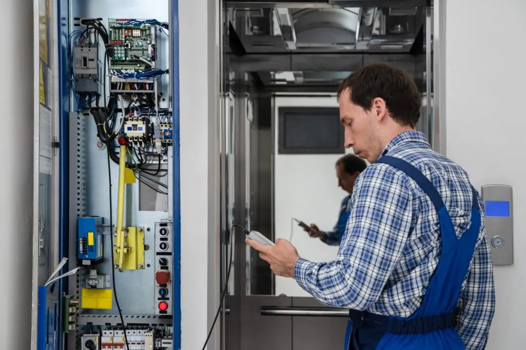
کدهای خطای زیما که هنگام عیبیابی فیدبک باید بشناسیم
در دفترچه سری L، چند خطا در بخش عیبیابی فرآیند AutoTune موتور سنکرون معرفی شدهاند.
وجود این خطاها بهتنهایی ثابت نمیکند علت لرزش کابین مشخص شده است؛ اما میتواند در تشخیص ایراد سیستم فیدبک یا راهاندازی مفید باشد.
| کد خطا | مفهوم در دفترچه زیما | بخش نیازمند بررسی |
|---|---|---|
noPG | متصل نبودن یا شناسایینشدن کارت PG | اتصال کارت PG، کابل رابط و پورت مرتبط |
PGO | قطع یا دریافتنشدن سیگنال انکودر | اتصال انکودر به کارت PG و سلامت فیدبک |
Auto | ناموفقبودن عملیات AutoTune در شرایط توضیحدادهشده در دفترچه | وضعیت حرکت موتور، ترمز و مجموعه مکانیکی |
در مستندات زیما، خطای Auto هنگام AutoTune موتور گیرلس میتواند با حرکتنکردن موتور در مرحله تعیینشده ارتباط داشته باشد؛ بنابراین وضعیت سیستم تعلیق، آزادشدن ترمز و گیر مکانیکی نیز از موارد مورد بررسی هستند.
نکته مهم این است که این جدول جایگزین فهرست کامل خطاهای درایو نیست. معنی هر خطا باید با توجه به مدل دستگاه، مرحله عملکرد و نسخه معتبر دفترچه تفسیر شود.
علت لرزش آسانسور هنگام توقف و تراز طبقه
ضربه یا لرزش هنگام توقف همیشه به معنای خرابی ترمز نیست.
در این مرحله، درایو باید کاهش سرعت را کنترل کند، کابین را به محدوده تراز طبقه برساند و فرایند پایان حرکت با ترتیب صحیح انجام شود.
برای تشخیص علت، ابتدا مشخص کنید ضربه در کدام لحظه رخ میدهد:
- هنگام آغاز کاهش سرعت؛
- هنگام ورود به سرعت پایین یا Leveling؛
- در لحظه رسیدن به تراز طبقه؛
- پس از توقف و درگیرشدن ترمز مکانیکی.
تنظیمات کاهش سرعت و Jerk توقف
در دفترچه سری L زیما، پارامترهای زیر با پروفیل کاهش سرعت مرتبطاند:
| پارامتر | عملکرد |
|---|---|
PA11 | Deceleration یا شتاب کاهش سرعت |
PA12 | Jerk 3 در ابتدای کاهش سرعت |
PA13 | Jerk 4 در انتهای کاهش سرعت |
اگر شکل پروفیل کاهش سرعت با مشخصات سیستم هماهنگ نباشد، امکان ایجاد تکان هنگام کاهش سرعت وجود دارد.
بااینحال، تغییر این پارامترها بدون بررسی روش توقف انتخابشده، همیشه مؤثر نیست.
نقش تنظیمات Leveling در لرزش آسانسور
در مرحله Leveling، کابین با سرعت کنترلشده به تراز طبقه نزدیک میشود.
در دفترچه سری L، پارامتر PA04 برای Leveling Speed معرفی شده است.
همچنین زیما دو روش توقف مرتبط با PA10 را توضیح میدهد:
روش Distance Approach: از اطلاعات فاصلههای تعریفشده با PA08 و PA09 استفاده میکند.
روش Deceleration: پروفیل کاهش سرعت را با پارامترهای PA11 تا PA13 کنترل میکند.
اگر کابین هنگام نزدیکشدن به طبقه ضربه میزند، باید روش توقف انتخابشده، وضعیت سنسورهای مرتبط، سرعت Leveling و اطلاعات فاصله بررسی شوند.
این بررسی مخصوصاً زمانی اهمیت دارد که مشکل در برخی طبقات شدیدتر از سایر طبقات باشد.
تفاوت ترمز مکانیکی و مقاومت ترمز درایو
یکی از اشتباهات رایج در عیبیابی آسانسور، یکسان درنظرگرفتن ترمز مکانیکی و مقاومت ترمز دینامیکی است.
ترمز مکانیکی بخشی از سیستم نگهداری و توقف موتور است و باید مطابق طراحی و الزامات ایمنی آسانسور عمل کند.
در مقابل، مقاومت ترمز دینامیکی در سیستمهای مجهز به این قطعه، انرژی الکتریکی برگشتی هنگام کاهش سرعت را به گرما تبدیل میکند.
به همین دلیل، ضربه ناشی از عملکرد ترمز مکانیکی لزوماً با تغییر مقاومت ترمز برطرف نمیشود.
همچنین مشکلات مدار ترمز دینامیکی میتوانند با خطاهای الکتریکی یا اختلال در فرآیند کاهش سرعت همراه باشند، بدون آنکه علت اصلی ضربه مکانیکی باشند.
بررسی تخصصی لرزش با درایوهای آسانسوری زیما سری L
درایو کنترل سرعت یکی از اجزای مهم کیفیت حرکت آسانسورهای کششی است.
این تجهیز با کنترل سرعت و گشتاور موتور، در اجرای پروفیل شتابگیری، حرکت، کاهش سرعت و توقف نقش دارد.
خانواده درایوهای آسانسوری و بالابر زیما سری L برای کاربردهای مرتبط با کنترل حرکت طراحی شدهاند.
بااینحال، امکانات کنترلی دستگاههای L100 و L200 یکسان نیست و هنگام عیبیابی باید مدل دقیق درایو مشخص باشد.
تفاوت L100 و L200 در عیبیابی لرزش
براساس جدول ویژگیهای دفترچه رسمی زیما، باید میان سه پیکربندی زیر تفاوت قائل شد:
| ویژگی | L100 | L200 گیربکس | L200 گیرلس |
|---|---|---|---|
| کاربرد اصلی موتور | القایی | القایی | سنکرون مغناطیس دائم |
| حالت کنترل | حلقهباز | حلقهبسته در پیکربندی مربوط | حلقهبسته با فیدبک مناسب |
| استفاده از انکودر در کنترل حلقهبسته | جزو قابلیتهای معرفیشده L100 نیست | پشتیبانی میشود | پشتیبانی میشود |
| ترتیب ترمز مخصوص آسانسور | دارد | دارد | دارد |
| کنترل بهره پیشرفته | در جدول قابلیتهای مشترک نیست | دارد | دارد |
| تعیین جهت و آفست انکودر | ندارد | قابلیت مرتبط دارد | قابلیت مرتبط دارد |
| Direct Approach | ندارد | در جدول رسمی برای این ستون علامتگذاری نشده | در جدول رسمی معرفی شده |
در مدل L100، بررسی اطلاعات موتور، شرایط مکانیکی، ترتیب ترمز و پروفیل حرکت اهمیت دارد.
در L200 با کنترل حلقهبسته، علاوه بر عوامل فوق، سلامت فیدبک انکودر و تنظیمات کنترلر نیز باید بررسی شوند.
در کاربردهای گیرلس، صحت اطلاعات موتور سنکرون و وضعیت فیدبک موقعیت اهمیت بیشتری پیدا میکند.
برای شناخت تنظیمات پایه و پارامترهای حرکتی مدل L100، میتوانید به مقاله آموزش تنظیمات درایو زیما L100 مراجعه کنید.
جدول پارامترهای مهم سری L در بررسی لرزش
جدول زیر برای شناسایی بخشهای مرتبط دفترچه تهیه شده است و به معنی توصیه به تغییر پارامترها نیست.
| پارامتر | عملکرد مستند | ارتباط با لرزش |
|---|---|---|
PA04 | Leveling Speed | رفتار کابین در مرحله تراز طبقه |
PA05 | Acceleration | کیفیت شتابگیری |
PA06 و PA07 | Jerk 1 و Jerk 2 | تغییر شتاب در شروع حرکت |
PA10 | Stop Method | انتخاب روش توقف |
PA11 تا PA13 | Deceleration و Jerk 3/4 | کیفیت کاهش سرعت |
PA14 | Brake on Delay | زمانبندی اولیه در ترتیب ترمز |
PA15 | Brake off Delay | زمانبندی ادامه PWM پس از توقف و فرمان ترمز |
PA16 | Brake Start Delay | ارتباط زمانی شروع PWM و آزادشدن ترمز |
PA23 | Mechanical Brake Enable | آستانه سرعت فعالشدن ترمز مکانیکی |
PE01 | Control Mode | انتخاب حالت کنترلی سازگار با موتور |
PE02 | Controller Bandwidth | پهنای باند اصلی کنترلر حلقهبسته |
PE10 و PE11 | Position Lock Time | زمان قفل موقعیت در شروع و توقف |
PE13 | Start Lock Mode | انتخاب حالت کنترل ضدعقبگرد در پیکربندی مربوط |
پارامترهای گروه PE در شرایط و حالتهای کنترلی مشخص کاربرد دارند. نام پارامترها و قابلیتهای در دسترس نیز باید با مدل و نسخه نرمافزار دستگاه تطبیق داده شوند.
برای بررسی توضیحات دقیق، محدودیتها و نمودار ترتیب عملکرد ترمز، از دفترچه رسمی نصب و راهاندازی درایو زیما سری L استفاده کنید.
چرا تغییر تصادفی پارامترهای درایو، لرزش آسانسور را برطرف نمیکند؟
در بعضی موارد تلاش میشود با تغییر پیدرپی شتاب، Jerk یا بهره کنترلر، لرزش کابین کاهش پیدا کند.
این روش ممکن است رفتار سیستم را تغییر دهد، اما بدون شناخت علت واقعی، لزوماً مشکل را برطرف نمیکند.
برای مثال، اگر ارتعاش ناشی از لقی کوپلینگ انکودر باشد، تغییر بهره کنترلر ممکن است نوسان مشاهدهشده را موقتاً تغییر دهد، درحالیکه ایراد مکانیکی همچنان وجود دارد.
همچنین اگر ترمز بهدرستی آزاد نمیشود، تغییر پروفیل شتاب جایگزین بررسی و تعمیر ترمز نیست.
به همین دلیل، عیبیابی باید ابتدا با بررسی علائم، شرایط مکانیکی، اطلاعات موتور و سوابق خطا آغاز شود و سپس به تنظیمات تخصصی درایو برسد.
روش تخصصی اندازهگیری و ثبت لرزش آسانسور
در عیبیابی حرفهای، توصیفهایی مانند «لرزش زیاد است» یا «کابین خوب حرکت نمیکند» برای مقایسه دقیق کافی نیستند.
ثبت شرایط وقوع لرزش و استفاده از ابزار اندازهگیری مناسب میتواند کیفیت تشخیص را افزایش دهد.
برای نمونه، اطلاعات زیر ارزش ثبت دارند:
| داده موردنیاز | کاربرد در عیبیابی |
|---|---|
| محل وقوع لرزش | تفکیک مشکل موضعی از مشکل سراسری |
| جهت حرکت | بررسی تفاوت رفتار در مسیر رفت و برگشت |
| وضعیت بار | شناسایی الگوی وابسته به بار |
| مرحله حرکت | تشخیص ارتباط احتمالی با شتاب، سرعت ثابت یا توقف |
| سرعت واقعی و فرمانی | بررسی نوسان کنترل سرعت |
| جریان یا گشتاور قابل مانیتور | ارزیابی رفتار موتور در صورت دسترسی |
| کدهای خطا | شناسایی مسیر بررسی تجهیزات و فیدبک |
| دادههای ارتعاش سهمحوره | ارزیابی کیفیت حرکت با ابزار تخصصی |
چه تفاوتی میان لرزش جانبی و عمودی وجود دارد؟
لرزش جانبی میتواند با تجهیزات راهنمای کابین، ریلها و اتصالات مکانیکی ارتباط داشته باشد.
در مقابل، لرزش عمودی ممکن است با کنترل حرکت، سیستم تعلیق یا عملکرد مجموعه محرکه مرتبط باشد.
بااینحال، ارتعاش مکانیکی و کنترلی میتواند در چند محور ظاهر شود و تشخیص قطعی تنها بر اساس جهت لرزش صحیح نیست.
بنابراین بهتر است دادههای اندازهگیری در کنار وضعیت موتور، فیدبک و شرایط مکانیکی تحلیل شوند.
چکلیست عیبیابی لرزش آسانسور برای تکنسینها
برای جلوگیری از بررسیهای تکراری و تغییرات غیرضروری، میتوان مسیر عیبیابی را در چند مرحله سازماندهی کرد.
مرحله اول: تعیین نوع و زمان لرزش
مشخص کنید لرزش در استارت، هنگام شتابگیری، در سرعت ثابت یا نزدیک توقف ایجاد میشود.
همچنین بررسی شود مشکل در تمام طبقات وجود دارد یا به یک موقعیت مشخص وابسته است.
مرحله دوم: بررسی شرایط مکانیکی
وضعیت ریلها، کفشکها، اتصالات، مجموعه محرکه، فلکهها، سیستم تعلیق و ترمز توسط متخصص ارزیابی شود.
در صورت مشاهده نقص مؤثر بر ایمنی، ادامه بهرهبرداری نباید انجام شود.
مرحله سوم: ثبت مشخصات موتور و درایو
مدل دقیق درایو، نوع موتور، حالت کنترل، اطلاعات پلاک و نسخه نرمافزار ثبت شود.
برای سیستمهای حلقهبسته، مشخصات انکودر و کارت فیدبک نیز باید در نظر گرفته شود.
مرحله چهارم: بررسی فیدبک و سوابق خطا
خطاهای ثبتشده، سلامت ارتباط انکودر و اطلاعات مانیتورینگ مرتبط بررسی شوند.
در این مرحله، وجود خطای فیدبک یا اختلاف سرعت میتواند مسیر بررسی را مشخصتر کند.
مرحله پنجم: تطبیق رفتار سیستم با مستندات
پس از شناخت منشأ احتمالی، بخش مربوط به ترمز، پروفیل حرکت یا کنترل موتور در دفترچه معتبر دستگاه بررسی شود.
هرگونه تغییر فنی باید توسط فرد واجد صلاحیت، مطابق دستورالعمل سازنده و با رعایت الزامات ایمنی انجام شود.
مرحله ششم: ارزیابی نتیجه پس از رفع عیب
پس از تعمیر یا اصلاح تأییدشده، عملکرد سیستم باید در شرایط آزمون مجاز و تحت نظارت متخصص ارزیابی شود.
هدف فقط حذف لرزش محسوس نیست؛ بلکه دستیابی به حرکت پایدار، توقف صحیح و حفظ الزامات ایمنی آسانسور است.
چه زمانی لرزش آسانسور خطرناک است؟
همه لرزشها شدت یکسانی ندارند، اما بعضی نشانهها نیازمند اقدام فوری هستند.
لرزش شدید و ناگهانی، حرکت ناخواسته کابین، عقبگرد غیرعادی، صدای شدید فلزی، توقف نامنظم یا وجود خطاهای تکرارشونده در سیستم حرکت از جمله مواردی هستند که باید جدی گرفته شوند.
در این شرایط، آسانسور نباید تا زمان بررسی فنی و تأیید ایمنی به بهرهبرداری عادی بازگردد.
مسافران و مدیران ساختمان نیز نباید برای رفع مشکل، تنظیمات درایو، مدارهای ترمز یا تجهیزات ایمنی را تغییر دهند.
چگونه از لرزش مجدد کابین آسانسور جلوگیری کنیم؟
پیشگیری از لرزش به نگهداری منظم مجموعه مکانیکی و کنترل حرکت وابسته است.
بازرسی دورهای ریلها و کفشکها، بررسی ترمز، وضعیت موتور و فلکهها، سلامت کابلها و اتصالات فیدبک و ثبت تغییرات کیفیت حرکت میتواند به شناسایی زودهنگام ایرادها کمک کند.
در زمان تعویض موتور، تابلو فرمان، انکودر یا درایو نیز باید سازگاری تجهیزات و صحت اطلاعات کنترلی بررسی شود.
اگر در مرحله انتخاب یا جایگزینی درایو هستید، مطالعه راهنمای انتخاب اینورتر آسانسور میتواند برای شناخت کاربرد درایو در سیستمهای گیربکس و گیرلس مفید باشد.
سوالات متداول درباره علت لرزش آسانسور
علت لرزش کابین آسانسور هنگام حرکت چیست؟
مشکلات ریل و کفشک، خرابی قطعات مجموعه محرکه، کشش نامتعادل سیمبکسلها یا نوسان کنترل سرعت موتور از دلایل احتمالی هستند. زمان و محل وقوع لرزش در تشخیص نقش مهمی دارد.
چرا آسانسور هنگام شروع حرکت ضربه میزند؟
ناهماهنگی عملکرد ترمز و گشتاور موتور، تنظیمات نامناسب شتاب و Jerk یا مشکلات مکانیکی میتوانند باعث ضربه اولیه شوند. بررسی باید مشخص کند مشکل از ترمز، موتور، درایو یا مجموعه مکانیکی است.
علت لرزش آسانسور هنگام توقف چیست؟
پروفیل نامناسب کاهش سرعت، مشکلات تراز طبقه و عملکرد نامناسب ترمز از عوامل احتمالی هستند. ابتدا باید مشخص شود ضربه هنگام کاهش سرعت، در لحظه توقف یا پس از توقف رخ میدهد.
آیا خرابی انکودر باعث لرزش آسانسور میشود؟
بله. در سیستمهای حلقهبسته، اختلال سیگنال انکودر میتواند کنترل سرعت و گشتاور موتور را دچار مشکل کند. وضعیت اتصال، کابل، کارت PG و اطلاعات فیدبک باید بررسی شود.
آیا تنظیم درایو میتواند لرزش کابین را کاهش دهد؟
اگر علت لرزش به کنترل سرعت، شتاب یا گشتاور مرتبط باشد، اصلاح تخصصی تنظیمات میتواند مؤثر باشد. اما در صورت وجود ایراد مکانیکی، تغییر پارامترهای درایو جایگزین تعمیر تجهیزات نیست.
چرا آسانسور فقط در بعضی طبقات میلرزد؟
وجود مشکل در ریلها، کفشکها یا اتصالات یک محدوده از چاه از احتمالات مهم است. همچنین شرایط فرمان و تجهیزات وابسته به موقعیت کابین باید بررسی شوند.
آیا لرزش آسانسور هیدرولیک هم به درایو مربوط است؟
لرزش در آسانسور هیدرولیک ممکن است به مجموعه پمپ، شیرهای کنترل، شرایط فشار، اتصالات یا تجهیزات مکانیکی مربوط باشد. بنابراین روشهای عیبیابی درایو آسانسور کششی را نمیتوان مستقیماً به همه سیستمهای هیدرولیک تعمیم داد.
جمعبندی؛ رفع لرزش آسانسور از تشخیص درست شروع میشود
علت لرزش آسانسور میتواند مکانیکی، الکتریکی یا ترکیبی از هر دو باشد. تنظیم نبودن ریل و کفشک، مشکلات موتور و فلکه، اختلال ترمز، فیدبک نامناسب انکودر و تنظیمات ناهماهنگ درایو از عوامل مهمی هستند که باید بررسی شوند.
برای رسیدن به تشخیص صحیح، ابتدا زمان و شرایط وقوع لرزش را مشخص کنید. سپس وضعیت مکانیکی و عملکرد سیستم کنترل را با اطلاعات واقعی دستگاه مقایسه کنید.
در آسانسورهای مجهز به درایو، کیفیت حرکت به هماهنگی پروفیل شتاب، کنترل گشتاور، عملکرد ترمز و صحت اطلاعات موتور وابسته است.
خانواده درایوهای سری L زیما امکاناتی برای کنترل حرکت در کاربردهای آسانسوری ارائه میکند؛ اما عملکرد مناسب آنها به انتخاب صحیح تجهیزات، راهاندازی اصولی و سلامت کل مجموعه وابسته است.
برای بررسی مدلها و مشخصات فنی، به دسته محصولات درایو آسانسور و بالابر زیما سری L مراجعه کنید.
Elevator vibration is not always caused by a faulty motor or variable frequency drive (VFD). Misaligned guide rails, worn guide shoes, brake timing problems, unstable motor torque, encoder feedback issues, and unsuitable acceleration or deceleration settings can all contribute to cabin vibration and jerky movement.
The first step in diagnosing elevator vibration causes is to identify exactly when the problem occurs. Does the cabin shake at startup, during acceleration, at constant speed, or when approaching a floor?
For example, a sudden jolt immediately after the elevator starts may indicate poor coordination between the mechanical brake and motor torque. By contrast, vibration that repeatedly occurs at the same position in the hoistway may point toward guide rail alignment, guide shoes, or mechanical connections.
This guide examines the mechanical and control-related causes of elevator cabin vibration, explains how to distinguish between different symptoms, and covers the relevant motor, brake, encoder, and VFD settings used in XIMA elevator drives.
Safety notice: If an elevator experiences severe vibration, unexpected cabin movement, abnormal rollback, or unreliable stopping, it should be taken out of normal service until a qualified elevator technician has identified the cause and confirmed that the equipment is safe. This guide is intended for technical understanding and professional troubleshooting. It does not authorize experimental changes to brake settings or safety systems.
Elevator Vibration Causes: Where Should Troubleshooting Begin?
Before opening equipment or modifying drive parameters, determine when and under what conditions the vibration occurs.
The timing, direction, and location of the disturbance can narrow the list of possible causes considerably.
Common Symptoms and What to Check First
- A sudden jolt when the elevator starts: Possible causes include incorrect brake-to-torque coordination or unsuitable acceleration settings. Inspect the mechanical brake and movement command sequence.
- Vibration during acceleration: Possible causes include inappropriate jerk settings, incorrect motor data, or mechanical problems. Examine the acceleration profile and traction system.
- Shaking at constant speed: Possible causes include guide rails, guide shoes, bearings, traction sheaves, or motor-speed fluctuations. Check both mechanical components and speed feedback.
- Vibration at low speed: Possible causes include unstable motor control, encoder feedback problems, or mechanical friction. Examine the control system and mechanical condition.
- Jerking when approaching a floor: Possible causes include incorrect deceleration or leveling settings. Check the deceleration profile and floor-leveling process.
- A sudden movement immediately after stopping: Possible causes include improper mechanical brake engagement or incorrect torque-removal timing. Inspect the brake sequence.
- Vibration at a particular hoistway position: Possible causes include local guide rail, bracket, or guide shoe problems. Inspect the affected section.
- Vibration that changes with cabin load: Possible causes include suspension conditions, load balance, motor torque, or brake behavior. Compare the symptoms under different loading conditions.
These observations help establish a troubleshooting direction; they do not provide a definitive diagnosis.
Mechanical and electrical problems can also occur simultaneously.
Main Mechanical Causes of Elevator Cabin Vibration
In many elevators, vibration originates in the mechanical system and is transmitted to the cabin through the suspension equipment, guide assembly, or traction system.
When this happens, changing VFD parameters without correcting the mechanical problem is unlikely to provide a reliable solution.
1. Misaligned Elevator Guide Rails
Guide rails define the movement path of the cabin and counterweight.
Poor rail alignment, damaged rail surfaces, loose connections, incorrectly installed brackets, or irregularities at rail joints can make cabin movement less smooth.
One important symptom is vibration that repeatedly occurs at approximately the same height in the hoistway.
If the cabin runs smoothly through most of its travel but shakes when passing a specific location, that section of the rail system deserves closer inspection.
However, this symptom does not prove that the guide rails are defective. Position-dependent sensors, control commands, and other equipment may also influence elevator behavior.
A qualified technician should assess the rail system and related components before identifying the cause.
2. Worn or Poorly Adjusted Guide Shoes
Guide shoes help keep the cabin and counterweight aligned with their respective rails.
Excessive wear, mechanical clearance, incorrect adjustment, or problems with sliding and roller guide assemblies can produce lateral vibration.
In elevators equipped with roller guides, the condition of the rollers and their bearings is particularly important.
It is also worth remembering that the source of vibration may not be located directly on the cabin.
Problems with counterweight guide assemblies can sometimes be transmitted through the suspension system and affect cabin movement.
3. Motor, Gearbox, Traction Sheave, and Bearing Problems
Worn bearings, misaligned drivetrain components, loose mechanical connections, and imbalance in rotating parts can generate vibration that changes with motor speed.
For example, if the frequency or intensity of the vibration increases as the motor accelerates, rotating components and mechanical connections should be investigated.
In geared elevator systems, the gearbox and associated couplings may also require inspection.
In gearless systems, the traction motor and sheave assembly are particularly important.
Mechanical noise accompanying vibration can provide an additional clue, but sound alone is not enough to identify a defective component.
4. Uneven Suspension Rope Tension
In traction elevators, improper differences in suspension rope tension may affect the behavior of the suspension system and traction sheaves.
Inspection may include the suspension ropes, terminations, traction sheaves, and related equipment, following the manufacturer’s requirements.
Where compensation chains or compensation ropes are used, their mounting, connections, and movement should also be checked.
Technical observation: If vibration changes significantly between upward and downward travel, or becomes more noticeable with certain cabin loads, record those differences.
Load-dependent vibration patterns can help technicians investigate mechanical balance, friction, and torque-control behavior.
Why Does an Elevator Vibrate When Starting?
Startup vibration often feels like a sudden jolt, a brief shake, or an irregular movement as the cabin begins to travel.
In traction elevators equipped with a VFD, a smooth start depends on several actions occurring in the correct sequence:
- The motor must develop enough torque to control the load.
- The mechanical brake must release at the appropriate time.
- The drive must execute the intended acceleration profile.
Poor coordination between these actions may result in uncomfortable or abnormal movement.
Mechanical Brake and Motor Torque Coordination
Before the elevator begins moving, the motor must generate the torque needed to control the suspended load.
The mechanical brake release command must be coordinated with that torque.
If the brake releases before sufficient motor torque is available, the cabin may move briefly in an unintended direction.
Conversely, if the motor begins developing torque while the brake remains engaged, the drivetrain may experience additional mechanical stress, noise, or a sudden jolt.
For this reason, startup troubleshooting should evaluate both the drive command sequence and the actual mechanical response of the brake.
An important distinction: An electrical command to release the brake does not necessarily mean that the brake has released immediately or completely.
The brake’s mechanical response time, coil condition, friction components, and overall mechanical condition also influence startup quality.
How Acceleration and Jerk Affect Elevator Ride Comfort
A VFD controls motor speed according to a defined movement profile.
Two important terms are acceleration and jerk:
- Acceleration: The rate at which speed changes over time, measured in metres per second squared (m/s²).
- Jerk: The rate at which acceleration changes over time, measured in metres per second cubed (m/s³).
High jerk can make changes in acceleration feel abrupt to passengers.
However, lowering jerk is not always the correct solution. The movement profile must remain compatible with the elevator’s rated speed, load conditions, motor, and mechanical design.
According to the XIMA L Series documentation, the relevant acceleration parameters include:
- PA05 — Acceleration: Defines the acceleration-related movement setting.
- PA06 — Jerk 1: Controls the change in acceleration at the beginning of the acceleration phase.
- PA07 — Jerk 2: Controls the change in acceleration toward the end of the acceleration phase.
The XIMA troubleshooting documentation associates startup vibration with settings such as Jerk 1 and Acceleration.
It also identifies an important diagnostic distinction: if the startup problem does not occur consistently at every floor, mechanical factors should also be investigated.
The underlying cause should therefore be established before altering the movement profile.
What Is Elevator Rollback at Startup?
Rollback is an unintended, short movement of the cabin in the opposite direction to the commanded travel direction as the elevator starts.
It is different from ordinary vibration.
Rollback may be associated with load imbalance, mechanical brake operation, or torque control during the transition from standstill to movement.
In closed-loop systems, the drive uses motor feedback to support more precise movement control.
The XIMA L Series documentation identifies several parameters associated with this process:
- PE10 and PE11: Position Lock Time settings associated with startup and stopping.
- PE13: Start Lock Mode, associated with anti-rollback control in compatible configurations.
These functions depend on the drive model and control mode. They should not be assumed to be available in every L Series drive.
Another important distinction concerns PA23.
In the XIMA manual, PA23 is identified as Mechanical Brake Enable and relates to the mechanical brake activation speed threshold.
It is not the same parameter as the selection of an anti-rollback control algorithm.
Distinguishing between brake sequencing and anti-rollback functions is essential during professional troubleshooting.
Why Does an Elevator Cabin Vibrate at Constant Speed?
If vibration continues after the acceleration phase has ended, mechanical and control-related causes should be assessed separately.
Startup settings are only one part of the movement-control system and may have little to do with vibration during steady travel.
Mechanical Vibration vs Motor Speed Fluctuation
A useful first diagnostic step is to compare actual motor behavior with the vibration felt inside the cabin.
If the measured motor speed fluctuates, the technician should investigate potential problems with:
- Motor parameter configuration
- Encoder feedback
- Closed-loop control settings
- Other relevant motor-control functions
If actual motor speed remains relatively stable but the cabin continues to vibrate, mechanical causes become more important to investigate.
These may include the suspension system, guide rails, guide shoes, and traction equipment.
This distinction is not absolute.
Mechanical vibration can sometimes influence the feedback signal or motor-control response.
For more reliable diagnosis, monitored drive data should be compared with measurements of actual cabin vibration and motor speed.
What Is Mechanical Resonance in an Elevator?
Mechanical resonance can occur when the excitation frequency generated by the motor or traction system approaches one of the natural frequencies of the mechanical structure.
Under these conditions, vibration amplitude may increase significantly.
For example, an elevator might vibrate noticeably within a particular speed range but run more smoothly at both lower and higher speeds.
This pattern can suggest a possible resonance problem.
However, it should be evaluated together with the condition of structural components, rotating assemblies, mechanical connections, and motor control.
The XIMA L Series documentation also discusses mechanical shock and vibration and the use of suitable vibration-reduction arrangements around the motor installation.
Any changes to vibration isolators or structural connections must be based on appropriate engineering design.
Installing flexible components in elevator traction equipment without proper evaluation is not a safe troubleshooting method.
Can PWM Carrier Frequency Cause Elevator Vibration?
The PWM carrier frequency affects the switching characteristics of a VFD and may influence the audible electromagnetic noise generated by the motor.
In many applications, a higher carrier frequency can reduce certain types of motor noise.
However, audible motor noise and physical cabin vibration are not the same problem.
Increasing carrier frequency can also affect inverter losses and thermal performance.
Any adjustment must remain within the limits specified for the drive model and installation conditions.
Practical takeaway: Before changing PWM carrier frequency, establish whether the problem is electromagnetic motor noise or actual mechanical vibration transmitted to the elevator cabin.
Can Encoder Problems Cause Elevator Cabin Vibration?
Yes. In closed-loop elevator systems, the encoder provides motor-speed feedback and, in certain applications, position information to the drive.
The VFD uses this feedback to compare actual motor operation with the commanded movement.
If encoder feedback is incorrect, unstable, or interrupted, speed and torque control may be affected.
Possible symptoms include:
- Low-speed vibration
- Motor-speed oscillation
- Irregular movement
- Unstable torque response
- Feedback-related fault indications
Common Causes of Encoder Feedback Problems
Several issues should be considered when inspecting the feedback system:
- Incorrect encoder installation or coupling alignment
- Damaged encoder cables or connectors
- Encoder cables routed too close to power cables
- Electromagnetic interference or inadequate cable shielding
- Encoder and PG card incompatibility
- Incorrect encoder or motor information configured in the drive
For closed-loop installations, the XIMA documentation emphasises proper encoder connections, shielded cables, separation from power wiring, and appropriate cable routing.
For certain gearless motor configurations, encoder offset and the accuracy of motor identification procedures are also important.
Why Should Encoder Feedback Be Checked Before Changing Controller Gain?
In a closed-loop system, unstable feedback may appear as oscillation in the speed-control response.
Changing controller gain without first checking feedback integrity can alter the symptoms without eliminating the underlying problem.
For example, a loose encoder coupling may produce irregular feedback even when the controller settings appear reasonable.
Before evaluating advanced control parameters, technicians should verify encoder connections, compatibility, and feedback quality using the procedures specified by the equipment manufacturer.
XIMA L Series Fault Codes Relevant to Encoder and Feedback Troubleshooting
The XIMA L Series manual identifies several fault indications associated with the synchronous motor AutoTune process.
These indications may help narrow the investigation, but they do not independently establish the cause of cabin vibration.
noPG — PG Card Not Connected or Recognised
This fault indication is associated with an unavailable or unrecognised PG card.
Relevant inspection points include:
- PG card installation
- Card connections
- Related communication or interface connections
PGO — Missing Encoder Signal
This indication is associated with the loss or absence of the expected encoder signal.
Relevant inspection points include:
- Encoder-to-PG card wiring
- Connectors
- Signal integrity
- Encoder feedback availability
Auto — Unsuccessful AutoTune Operation
This indication relates to an unsuccessful AutoTune operation under conditions described in the manual.
Depending on the stage involved, technicians may need to investigate:
- Whether the motor can move as required
- Mechanical brake release
- Traction-system condition
- Mechanical obstruction or binding
In the gearless motor AutoTune procedure, the XIMA documentation associates an Auto fault with situations in which the motor does not move during the required stage.
Important: These are not the complete fault codes for every XIMA elevator drive.
Each fault must be interpreted in the context of the exact model, operating stage, and applicable manual version.
Why Does an Elevator Vibrate or Jerk When Stopping?
An elevator that jolts near the end of travel does not necessarily have a defective brake.
During stopping, the drive must control deceleration, guide the cabin toward floor level, and coordinate the end of motor operation with the mechanical brake sequence.
The most useful first step is to identify exactly when the jolt occurs:
- At the beginning of deceleration
- During the transition to leveling speed
- As the cabin reaches floor level
- After motor movement has stopped and the mechanical brake engages
Each situation suggests a different troubleshooting direction.
Deceleration and Jerk Settings
The XIMA L Series manual identifies the following parameters:
- PA11 — Deceleration: Associated with the deceleration profile.
- PA12 — Jerk 3: Controls the change in acceleration at the beginning of the deceleration phase.
- PA13 — Jerk 4: Controls the change in acceleration toward the end of deceleration.
An unsuitable deceleration profile can contribute to abrupt movement as the elevator slows down.
However, adjusting these parameters may not be effective if the problem is related to the selected stopping method or another component of the system.
How Leveling Settings Affect Elevator Vibration
During leveling, the cabin approaches the required floor position at a controlled speed.
The XIMA L Series documentation identifies PA04 as the Leveling Speed parameter.
It also describes stopping methods associated with PA10.
These include:
- Distance Approach: Uses distance-related settings such as PA08 and PA09.
- Deceleration: Uses the deceleration profile associated with PA11 through PA13.
If the cabin jolts when approaching a floor, technicians should examine the selected stopping method, related sensors, leveling speed, and distance settings.
This is particularly relevant if the problem is more noticeable at certain floors than at others.
Mechanical Brake vs Dynamic Braking Resistor
A common troubleshooting mistake is treating the mechanical brake and dynamic braking resistor as if they perform the same function.
They do not.
Mechanical brake: Part of the elevator’s mechanical holding and stopping arrangement. Its operation must comply with the elevator’s design and applicable safety requirements.
Dynamic braking resistor: In systems equipped with this component, it dissipates regenerated electrical energy as heat during certain operating conditions, including deceleration.
A jolt caused by mechanical brake engagement will not necessarily be corrected by changing the braking resistor.
Likewise, a dynamic braking circuit problem may produce electrical faults or deceleration difficulties without being the direct cause of a mechanical braking jolt.
These systems must be diagnosed according to their actual functions.
Diagnosing Elevator Vibration With XIMA L Series Drives
The elevator VFD is an important component in controlling the movement quality of a traction elevator.
It regulates motor speed and torque during startup, acceleration, normal travel, deceleration, and stopping.
The XIMA L Series elevator and lift drives are designed for elevator and lifting applications.
However, L100 and L200 drives do not offer identical control capabilities.
The exact drive model must be identified before evaluating available parameters or selecting a troubleshooting procedure.
Understanding L100 and L200 Differences
The XIMA documentation distinguishes between L100 and different L200 configurations.
These differences are important because not all control functions are available in every model.
XIMA L100
- Primarily associated with induction motor applications.
- Uses the open-loop control configuration described for this model.
- Closed-loop encoder control is not listed among its stated L100 capabilities.
- Includes elevator-specific mechanical brake sequencing.
- Does not include the advanced controller gain functions listed for relevant L200 configurations.
- Encoder direction and offset functions are not identified as L100 features.
- Direct Approach is not listed as an L100 capability in the referenced feature comparison.
For L100 troubleshooting, motor specifications, mechanical condition, brake sequencing, and movement profiles are key areas of investigation.
XIMA L200 for Geared Elevator Motors
- Associated with induction motor applications.
- Supports the relevant closed-loop configuration.
- Supports encoder feedback in compatible installations.
- Includes elevator-specific mechanical brake sequencing.
- Provides advanced controller gain functions.
- Includes encoder direction and offset-related features.
- Direct Approach is not marked as available for this configuration in the referenced XIMA feature comparison.
For a closed-loop L200 installation, encoder condition and controller settings should be evaluated alongside the mechanical system.
XIMA L200 for Gearless Elevator Motors
- Associated with permanent magnet synchronous motor applications.
- Uses the relevant closed-loop motor-control configuration.
- Supports appropriate encoder feedback.
- Includes elevator-specific mechanical brake sequencing.
- Provides advanced controller gain functions.
- Includes relevant encoder direction and offset functions.
- Direct Approach is identified for the compatible gearless configuration in the official feature comparison.
In gearless applications, correct synchronous motor information and position feedback are especially important.
The availability of individual functions must always be confirmed against the exact product model and firmware version.
For an introduction to basic movement parameters and commissioning considerations, see the XIMA L100 Drive Setup and Troubleshooting Guide.
Important XIMA L Series Parameters for Vibration Diagnosis
The following parameters identify relevant sections of the XIMA manual.
They are provided for technical reference, not as instructions to modify an operating elevator.
- PA04 — Leveling Speed: Related to cabin movement while approaching floor level.
- PA05 — Acceleration: Related to acceleration behavior and ride quality.
- PA06 — Jerk 1: Controls changes in acceleration during the initial acceleration phase.
- PA07 — Jerk 2: Controls changes in acceleration toward the end of the acceleration phase.
- PA10 — Stop Method: Selects the relevant stopping approach.
- PA11 — Deceleration: Related to the deceleration profile.
- PA12 — Jerk 3: Controls changes in acceleration at the beginning of deceleration.
- PA13 — Jerk 4: Controls changes in acceleration toward the end of deceleration.
- PA14 — Brake on Delay: Associated with timing in the mechanical brake sequence.
- PA15 — Brake off Delay: Associated with the continuation of PWM output after stopping and the brake command.
- PA16 — Brake Start Delay: Associated with the timing relationship between the start of PWM output and brake release.
- PA23 — Mechanical Brake Enable: Defines the relevant speed threshold for mechanical brake activation.
- PE01 — Control Mode: Selects the motor-control mode supported by the configuration.
- PE02 — Controller Bandwidth: Associated with the main bandwidth setting of the closed-loop controller.
- PE10 and PE11 — Position Lock Time: Associated with position locking at startup and stopping.
- PE13 — Start Lock Mode: Selects the relevant anti-rollback control mode in compatible configurations.
The PE parameter group is applicable only under specific control conditions.
Parameter names, available features, and operating limits must be checked against the exact drive model and software version.
For detailed definitions, operating restrictions, and the brake sequence diagram, consult the official XIMA L Series installation and commissioning manual.
Why Randomly Changing VFD Parameters Does Not Fix Elevator Vibration
When an elevator vibrates, a technician may be tempted to adjust acceleration, jerk, or controller gain repeatedly until the movement feels smoother.
Although these changes can affect system behavior, they do not necessarily correct the cause of the problem.
For example, if the vibration is caused by excessive clearance in an encoder coupling, changing controller gain may temporarily alter the observed oscillation while the mechanical defect remains.
Similarly, if a mechanical brake does not release properly, changing the acceleration profile is not a substitute for inspecting and repairing the brake.
A reliable troubleshooting process should begin with:
- Identifying the symptoms and when they occur
- Inspecting the relevant mechanical components
- Verifying motor information
- Reviewing recorded fault indications
- Examining feedback integrity
- Comparing the observed behavior with the manufacturer’s documentation
Only after the probable cause has been established should qualified personnel consider adjustments to the relevant drive settings.
How to Measure and Record Elevator Vibration Professionally
Descriptions such as the elevator shakes badly or the cabin does not run smoothly may communicate the problem, but they are not sufficient for detailed comparison or technical diagnosis.
A more systematic approach involves recording the operating conditions and, where appropriate, using suitable vibration measurement equipment.
What Data Should Be Recorded?
- Location of vibration: Helps distinguish a localised hoistway problem from vibration occurring throughout the travel path.
- Travel direction: Helps identify differences between upward and downward movement.
- Cabin load: Reveals whether vibration depends on loading conditions.
- Movement phase: Identifies whether the disturbance occurs during startup, acceleration, constant-speed travel, or stopping.
- Commanded and actual motor speed: Helps assess potential speed-control fluctuations.
- Available motor current or torque monitoring data: Supports evaluation of motor behavior where such measurements are provided.
- Recorded fault codes: Helps identify potential feedback, motor-control, or equipment problems.
- Three-axis vibration measurements: Provides additional information for assessing cabin ride quality.
These observations become more useful when they can be compared across repeated trips under controlled conditions.
What Is the Difference Between Lateral and Vertical Elevator Vibration?
Lateral vibration may be associated with cabin guide equipment, guide rails, and related mechanical connections.
Vertical vibration may be associated with motion control, the suspension system, or the traction assembly.
However, mechanical and control-related disturbances can appear in multiple directions.
The direction of vibration alone does not provide a definitive diagnosis.
Measurement data should therefore be interpreted alongside motor behavior, feedback signals, and the condition of the mechanical system.
Elevator Vibration Troubleshooting Checklist for Technicians
A structured troubleshooting process helps avoid unnecessary inspections and uncontrolled parameter changes.
Step 1: Identify When and Where the Vibration Occurs
Determine whether the cabin vibrates:
- At startup
- During acceleration
- At constant speed
- During deceleration
- While leveling
- Immediately after stopping
Also record whether the problem occurs at every floor or only within a particular section of the hoistway.
Step 2: Inspect the Mechanical System
A qualified technician should assess the condition of the:
- Guide rails
- Guide shoes
- Mechanical connections
- Traction motor
- Traction sheaves
- Suspension system
- Mechanical brake
If a defect affecting safety is discovered, the elevator must not remain in normal operation.
Step 3: Record Motor and Drive Specifications
Document the exact:
- VFD model
- Motor type
- Control mode
- Motor nameplate information
- Drive software version
For closed-loop systems, also identify the encoder type and PG feedback card.
Step 4: Review Feedback and Fault History
Examine recorded fault codes and the condition of encoder connections.
Compare relevant monitoring information with the symptoms observed during travel.
A feedback fault or discrepancy in measured speed may help narrow the investigation.
Step 5: Compare System Behavior With the Manufacturer’s Documentation
Once the probable cause has been identified, review the relevant documentation for the:
- Mechanical brake sequence
- Motion profile
- Motor-control mode
- Encoder configuration
- Stopping method
Technical changes must be performed by qualified personnel following the manufacturer’s instructions and applicable safety requirements.
Step 6: Verify the Results After Corrective Work
After an approved repair or adjustment, the system should be evaluated under permitted test conditions and professional supervision.
The objective is not simply to eliminate noticeable vibration.
The elevator must also demonstrate stable movement, correct stopping behavior, and compliance with its safety requirements.
When Is Elevator Vibration Dangerous?
Not all vibration indicates the same level of risk.
However, certain symptoms require immediate professional attention.
These include:
- Sudden and severe cabin vibration
- Unintended cabin movement
- Abnormal rollback
- Loud metallic noises
- Irregular or unreliable stopping
- Repeated motion-system faults
Under these conditions, the elevator should not return to normal service until a qualified technician has completed the necessary inspection and confirmed its safety.
Passengers and building managers should never attempt to resolve these problems by modifying VFD settings, brake circuits, or safety equipment.
How Can Elevator Vibration Be Prevented?
Preventing recurring vibration depends on regular maintenance of both the mechanical system and the motion-control equipment.
Periodic inspections should include the condition of guide rails, guide shoes, mechanical brakes, motors, traction sheaves, suspension components, cables, and feedback connections.
Recording changes in ride quality can help identify developing problems before they become more serious.
When replacing the motor, control cabinet, encoder, or VFD, technicians should also verify equipment compatibility and the accuracy of motor-control information.
If a drive is being selected or replaced, the XIMA Elevator Inverter Selection Guide explains important selection considerations for geared and gearless elevator applications.
Frequently Asked Questions About Elevator Vibration
What Causes an Elevator Cabin to Vibrate During Travel?
Possible causes include guide rail alignment problems, worn guide shoes, defects in traction-system components, uneven suspension rope tension, and motor-speed fluctuations.
The timing and location of the vibration are important diagnostic clues.
Why Does an Elevator Jerk When Starting?
A sudden startup jolt may be caused by poor coordination between mechanical brake release and motor torque, unsuitable acceleration or jerk settings, or mechanical problems.
Diagnosis should establish whether the underlying issue lies in the brake, motor, drive, or mechanical assembly.
What Causes Elevator Vibration When Stopping?
Possible causes include an unsuitable deceleration profile, leveling problems, or incorrect mechanical brake operation.
The technician should first determine whether the jolt occurs during deceleration, at the moment of stopping, or immediately afterward.
Can a Faulty Encoder Cause Elevator Vibration?
Yes.
In closed-loop systems, incorrect encoder feedback can interfere with motor speed and torque control.
The encoder connections, cables, PG card, and feedback configuration should be inspected.
Can Adjusting a VFD Reduce Elevator Vibration?
If the vibration is genuinely caused by speed control, acceleration, or torque-control behavior, professionally verified adjustments may improve ride quality.
However, drive parameter changes cannot replace mechanical repairs when the source of vibration is a defective component.
Why Does an Elevator Vibrate Only at Certain Floors?
Problems with guide rails, guide shoes, or mechanical connections in a particular hoistway section may be responsible.
Position-dependent sensors and motion-control commands should also be investigated.
Is Vibration in a Hydraulic Elevator Also Related to the VFD?
Hydraulic elevator vibration may involve the pump assembly, hydraulic control valves, pressure conditions, mechanical connections, or other system components.
Troubleshooting procedures developed for traction elevator VFDs should not automatically be applied to every hydraulic elevator system.
Conclusion: Correct Elevator Vibration Diagnosis Comes First
Elevator vibration may be mechanical, electrical, or the result of several interacting problems.
Misaligned guide rails, worn guide shoes, traction-system defects, brake timing issues, unstable encoder feedback, and unsuitable VFD settings are among the important factors to investigate.
Accurate diagnosis begins by identifying when and under what conditions the vibration occurs.
The next step is to compare the mechanical condition of the elevator with actual motor, brake, and motion-control behavior.
In traction elevators equipped with variable frequency drives, ride quality depends on the coordination of acceleration profiles, torque control, brake sequencing, and accurate motor information.
XIMA L Series drives provide movement-control functions for compatible elevator and lifting applications. However, reliable operation depends on correct equipment selection, professional commissioning, and the condition of the entire elevator system.
For available models and technical specifications, explore the XIMA L Series elevator and lift inverter range.
محصولات
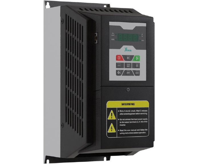
اینورتر 15 کیلووات سه فاز سری بالابر و جرثقیل
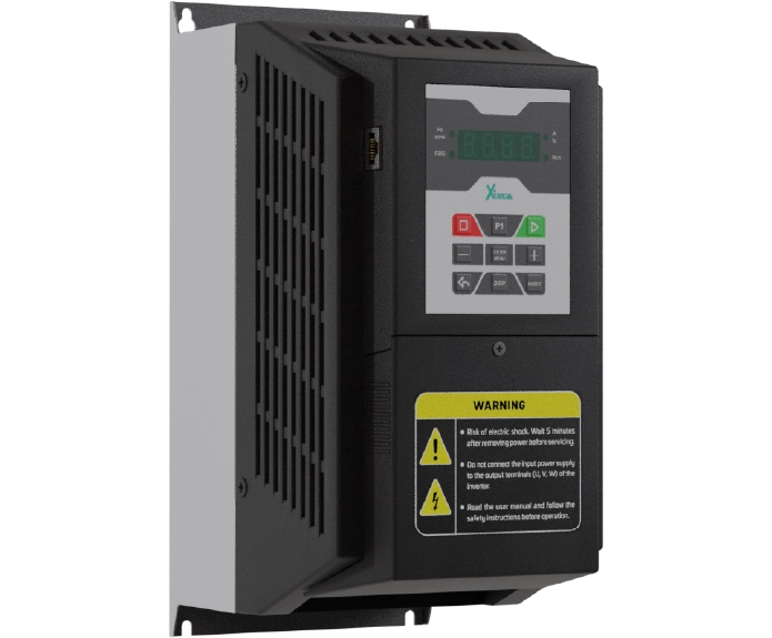
اینورتر 11 کیلووات سه فاز سری بالابر و جرثقیل
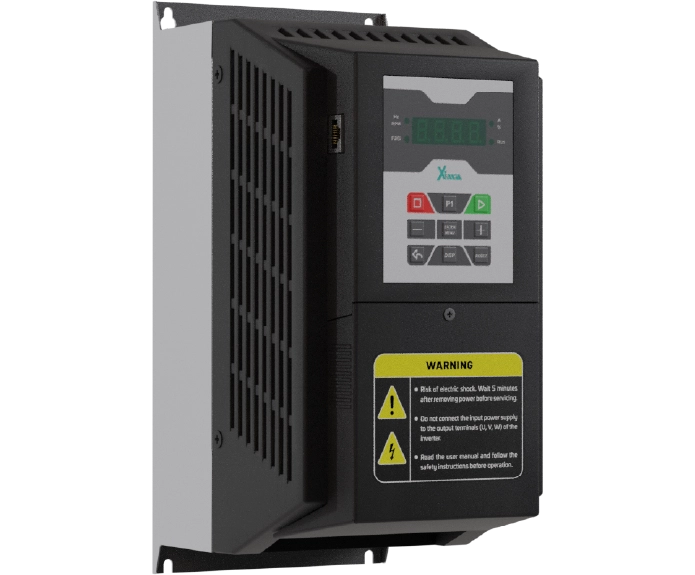
اینورتر 7.5 کیلووات سه فاز سری بالابر و جرثقیل
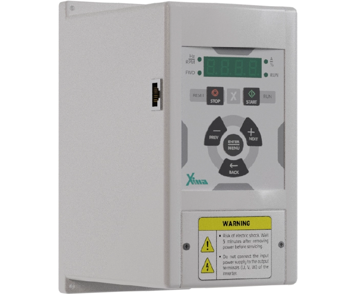
اینورتر 5.5 کیلووات سه فاز سری بالابر و جرثقیل
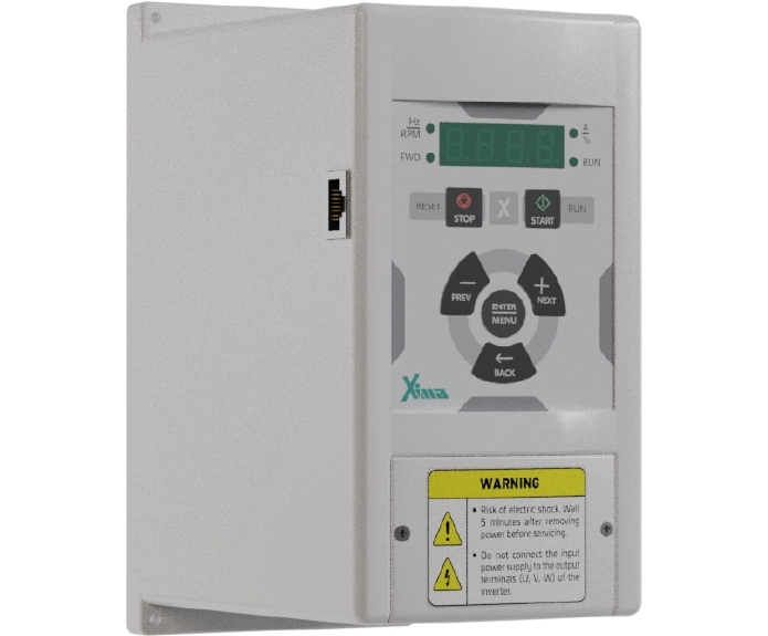
اینورتر 4 کیلووات سه فاز سری بالابر و جرثقیل
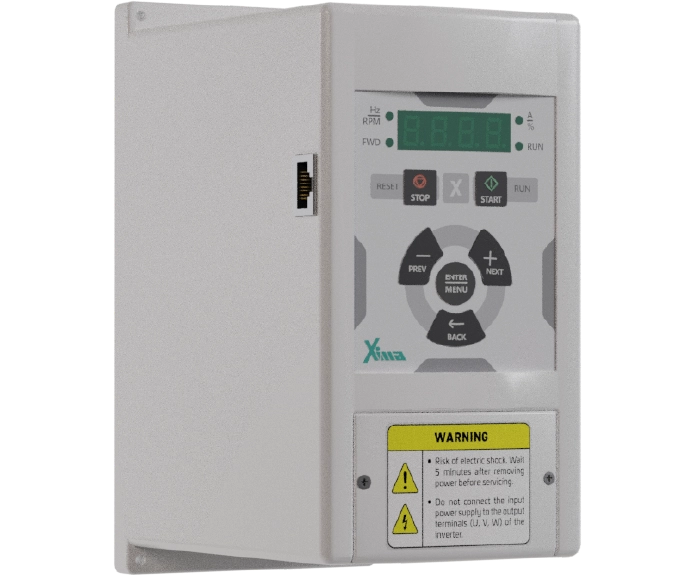
اینورتر 3 کیلووات سه فاز سری بالابر و جرثقیل
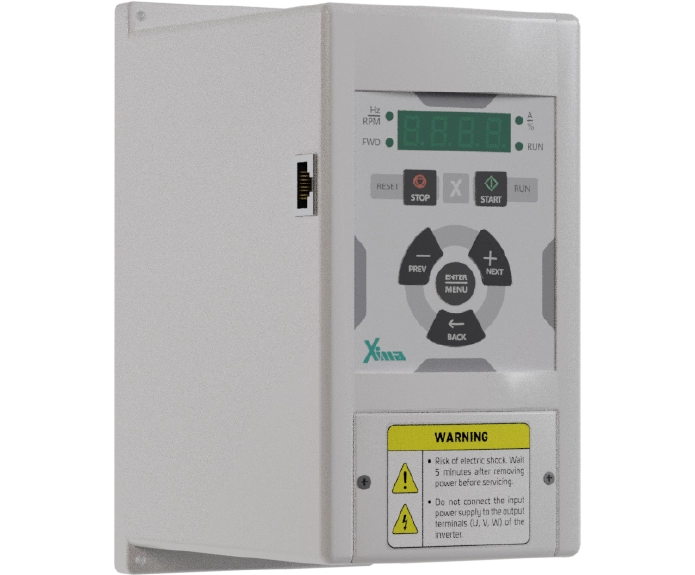
اینورتر 2.2 کیلووات سه فاز سری بالابر و جرثقیل
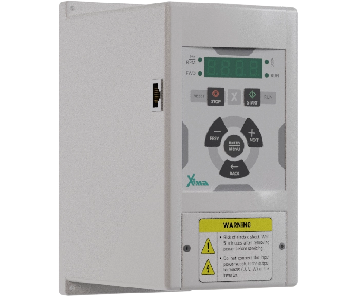
اینورتر 1.5 کیلووات سه فاز سری بالابر و جرثقیل
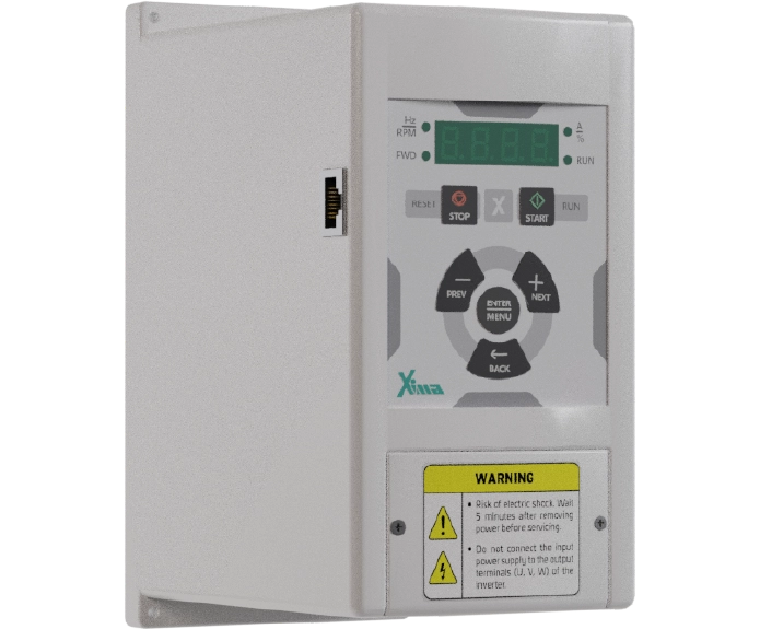
اینورتر 3 کیلووات تک فاز سری بالابر و جرثقیل
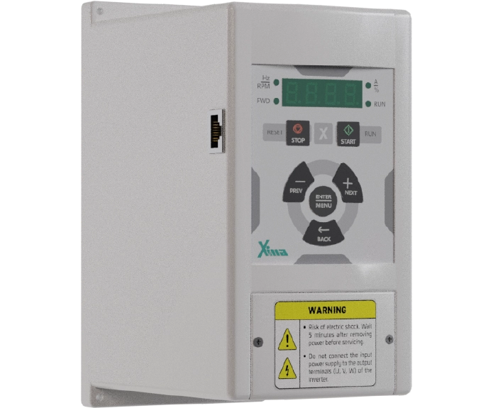
اینورتر 2.2 کیلووات تک فاز سری بالابر و جرثقیل
نظرات کاربران
دیدگاهها
هنوز دیدگاهی ثبت نشده است.