آموزش تنظیمات درایو زیما G100؛ راهاندازی و پارامترهای ضروری

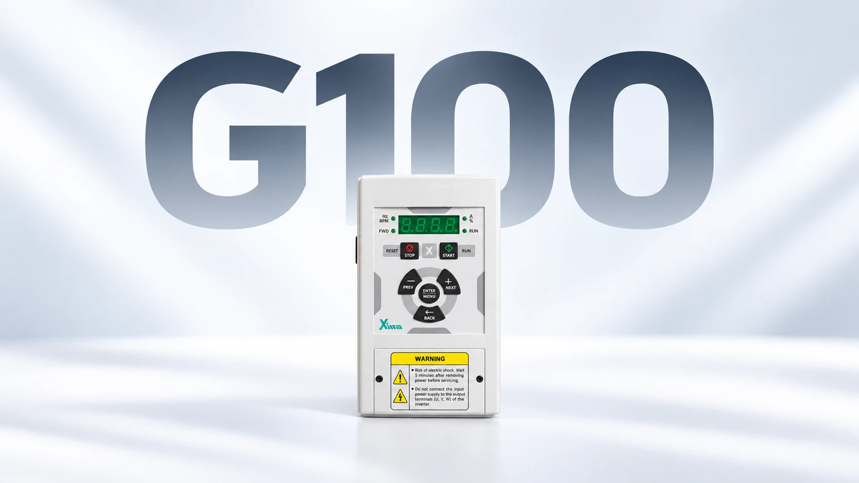
برای راهاندازی درایو زیما G100 چه تنظیماتی لازم است؟
آموزش تنظیمات درایو زیما G100 یکی از مهمترین مراحل برای راهاندازی صحیح موتورهای سهفاز در تجهیزات صنعتی است. برای استفاده از این درایو باید با نحوه ورود به منوی تنظیمات، پارامترهای راهاندازی، کنترل سرعت موتور و روشهای فرماندهی آشنا باشید.
در این مقاله، تنظیمات اینورتر زیما G100 را به زبان ساده و با استناد به راهنمای سری صنعتی G بررسی میکنیم. همچنین توضیح میدهیم که چطور فرکانس موتور را از طریق کیپد یا پتانسیومتر کنترل کنید، مشخصات موتور را در تنظیمات وارد کنید و مشکلات متداول هنگام راهاندازی را تشخیص دهید.
اگر دستگاه G100 در اختیار دارید، پیش از شروع، کد کامل مدل و نسخه نرمافزاری آن را بررسی کنید. مقادیر و نام نمایشی برخی پارامترها ممکن است در نسخههای مختلف متفاوت باشند.
برای دسترسی به راهنمای رسمی نیز میتوانید از ابتدای کار به صفحه مستندات زیما مراجعه کنید.
نکته ایمنی: این مطلب یک راهنمای آموزشی برای شناخت و انتخاب تنظیمات است. نصب، اتصال برق و موتور، اصلاح سیمکشی و تست عملی باید توسط متخصص برق صنعتی و مطابق دستورالعمل ایمنی دستگاه انجام شود.
خلاصه مراحل راهاندازی درایو زیما G100
اگر میخواهید بدانید برای اولین راهاندازی اینورتر زیما چه تنظیماتی لازم است، ابتدا مراحل اصلی زیر را بشناسید:
- مشخصات مدل درایو و پلاک موتور را بررسی کنید.
- از تطابق برق ورودی، ولتاژ خروجی و سربندی موتور اطمینان حاصل کنید.
- با کلیدهای کیپد و نحوه ورود به منوی تنظیمات آشنا شوید.
- روش دریافت فرمان استارت و استاپ را انتخاب کنید.
- منبع تعیین فرکانس و کنترل سرعت موتور را مشخص کنید.
- جریان نامی موتور و پارامترهای ضروری را تنظیم کنید.
- زمان شتابگیری و کاهش سرعت را متناسب با بار انتخاب کنید.
- پس از بررسی مدار و تجهیزات ایمنی، عملکرد دستگاه را در شرایط کنترلشده آزمایش کنید.
در ادامه، هر مرحله را بهصورت جداگانه توضیح میدهیم.
درایو زیما G100 چیست و چه کاربردی دارد؟
درایو زیما G100 یکی از مدلهای خانواده اینورتر صنعتی سری G شرکت زیما است که برای کنترل سرعت و عملکرد موتورهای القایی در کاربردهای صنعتی استفاده میشود.
این خانواده شامل مدلهایی با ورودی تکفاز ۲۲۰ ولت و مدلهایی با ورودی سهفاز ۳۸۰ ولت است. مدلهای تکفاز G100، خروجی سهفاز ۲۲۰ ولت دارند؛ بنابراین انتخاب آنها باید با ولتاژ و نحوه سربندی موتور هماهنگ باشد.
درایوهای G100 زیما در توانهای مختلف عرضه میشوند؛ از مدلهای کوچکتر مناسب تجهیزات سبک تا مدلهای دارای توان بالاتر برای کاربردهای صنعتی.
برخی از کاربردهای این درایو عبارتاند از:
- کنترل دور نوار نقاله
- راهاندازی موتور ماشینآلات صنعتی
- تنظیم سرعت میکسر و همزن صنعتی
- کنترل دور فن و تجهیزات تهویه
- راهاندازی برخی ماشینآلات دارای موتور سهفاز
قبل از تنظیم درایو زیما G100 چه اطلاعاتی لازم داریم؟
برای راهاندازی صحیح، ابتدا باید مشخصات موتور و دستگاهی که قرار است کنترل شود مشخص باشد.
اطلاعات موردنیاز معمولاً روی پلاک موتور و برچسب فنی درایو نوشته شدهاند.
| مشخصات | دلیل اهمیت |
|---|---|
| توان موتور (kW) | بررسی تناسب ظرفیت درایو و موتور |
| ولتاژ نامی موتور | تعیین سازگاری خروجی درایو و سربندی موتور |
| جریان نامی موتور (A) | تنظیم حفاظت و مشخصات نامی موتور |
| فرکانس نامی (Hz) | تنظیم مشخصات عملکرد موتور |
| سرعت نامی (RPM) | تنظیم پارامترهای موتور و تحلیل عملکرد |
| ضریب توان (Cos φ) | استفاده در تنظیمات موتور، در صورت نیاز |
| نوع بار مکانیکی | انتخاب شتاب، توقف و روش کنترل |
آیا توان درایو و موتور باید یکسان باشد؟
توان نامی یکی از معیارهای انتخاب اینورتر است، اما بهتنهایی کافی نیست.
برای مثال، یک موتور ۲٫۲ کیلووات متصل به یک فن ممکن است از نظر شرایط راهاندازی و تغییر سرعت با یک موتور ۲٫۲ کیلووات متصل به نوار نقاله بارگذاریشده تفاوت داشته باشد.
بنابراین علاوه بر توان باید جریان نامی موتور، اضافهبار موردنیاز، نوع کاربرد و شرایط کارکرد بررسی شوند.
تفاوت درایو زیما G100 تکفاز و سهفاز
درایو G100 با ورودی تکفاز ۲۲۰ ولت برای شرایطی طراحی شده که برق تکفاز در دسترس است اما باید یک موتور سهفاز ۲۲۰ ولت کنترل شود.
در مقابل، مدلهای G100 سهفاز برای تغذیه سهفاز ۳۸۰ ولت طراحی شدهاند.
برای مثال:
- مدل
G100B022-1دارای ورودی تکفاز ۲۲۰ ولت است. - مدل
G100B022-3دارای ورودی سهفاز ۳۸۰ ولت است.
هر دو مدل با توان نامی ۲٫۲ کیلووات در فهرست محصولات زیما قرار دارند؛ بااینحال، ولتاژ خروجی آنها یکسان نیست.
در زمان راهاندازی موتور سهفاز با برق تکفاز، توجه به همین تفاوت ضروری است.
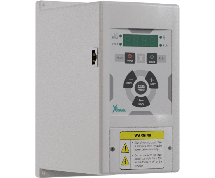
آشنایی با کیپد درایو زیما G100
یکی از اولین مراحل آموزش تنظیمات درایو زیما G100، شناخت صفحهکلید یا کیپد دستگاه است.
کیپد برای مشاهده وضعیت، ورود به منوی پارامترها، تغییر فرکانس و بررسی کدهای خطا استفاده میشود.
کلیدهای مهم در راهنماهای سری G شامل موارد زیر هستند:
| کلید | وظیفه |
|---|---|
| ENTER | ورود به پارامتر و ثبت مقدار |
| + | حرکت در منو یا افزایش مقدار |
| – | حرکت در منو یا کاهش مقدار |
| START | ارسال فرمان راهاندازی در حالت مجاز |
| STOP/RESET | توقف یا ریست خطا مطابق تنظیمات دستگاه |
| BACK | بازگشت به منوی قبلی |
چیدمان و نام کلیدها ممکن است با توجه به نسخه دستگاه متفاوت باشد.
نکته: کلید STOP کیپد، جایگزین مدار توقف اضطراری ایمن ماشینآلات نیست.
نحوه ورود به منوی تنظیمات درایو زیما G100
برای دسترسی به پارامترهای ضروری، در راهنمای سری G یک منوی راهاندازی سریع یا Quick Start در نظر گرفته شده است.
طبق دفترچه راهنمای سری G، منوی راهاندازی سریع از نسخه نرمافزاری 3.16 به بعد اضافه شده است.
در نسخههای دارای این منو، روش دسترسی به تنظیمات به این صورت است:
- ابتدا وضعیت دستگاه و نبود فرمان حرکت را بررسی کنید.
- کلید ENTER را حدود ۵ ثانیه نگه دارید.
- پس از نمایش منوی Quick Start، با کلیدهای + و – بین پارامترها جابهجا شوید.
- برای مشاهده یا ویرایش مقدار یک پارامتر، ENTER را فشار دهید.
- مقدار موردنظر را طبق راهنمای همان نسخه دستگاه تغییر دهید.
- برای ثبت مقدار، دوباره ENTER را فشار دهید.
- با کلید BACK از منوی راهاندازی سریع خارج شوید.
در مدلهای دارای نرمافزار قدیمیتر، ممکن است این منو وجود نداشته باشد و تنظیمات از مسیر دیگری انجام شوند.
تفاوت Quick Start و منوی اصلی پارامترها
منوی Quick Start برای دسترسی سادهتر به تنظیمات پرکاربرد راهاندازی طراحی شده است.
اما برای تغییر تنظیمات پیشرفتهتر مانند ورودی و خروجیهای کنترلی، پارامترهای ارتباطی، محدودیتها و برخی حفاظتها باید از منوی اصلی استفاده شود.
بنابراین اگر پارامتر موردنظر را در Quick Start پیدا نکردید، ابتدا دفترچه مدل دستگاه را بررسی کنید؛ ممکن است آن پارامتر در یکی از گروههای اصلی قرار داشته باشد.
جدول پارامترهای مهم درایو زیما G100
شناخت پارامترها مهمترین بخش تنظیمات اینورتر زیما است.
در جدول زیر، پارامترهای پرکاربرد راهاندازی سریع و تنظیمات اصلی سری G معرفی شدهاند.
| پارامتر | کاربرد |
|---|---|
drv / drU | انتخاب حالت فرمان راهاندازی در نمایشگرها و مستندات مربوط |
Frq / FrEQ | انتخاب منبع فرکانس |
ACC | تنظیم زمان شتابگیری در منوی سریع |
dEC | تنظیم زمان کاهش سرعت در منوی سریع |
Cur / rcur | تنظیم جریان نامی موتور |
drC / dirc | انتخاب جهت چرخش |
StoP | انتخاب روش توقف |
boSt | تنظیم بوست گشتاور |
Pr01 | حداقل فرکانس |
Pr02 | حداکثر فرکانس |
Pr03 | زمان شتابگیری در منوی اصلی |
Pr04 | زمان کاهش سرعت در منوی اصلی |
Pr05 | بوست ولتاژ |
rt01 | جریان نامی موتور |
rt02 | دور نامی موتور |
rt03 | ولتاژ نامی موتور |
rt04 | ضریب توان موتور |
rt05 | فرکانس نامی موتور |
این جدول با استفاده از مستندات خانواده G تهیه شده است. نام نمایشی، محدوده و گزینههای هر پارامتر را پیش از تغییر با دفترچه نسخه نرمافزاری همان G100 تطبیق دهید.
تنظیم روش فرمان درایو G100 با پارامتر drv
یکی از تنظیمات اولیه، تعیین روش دریافت فرمان حرکت موتور است.
این پارامتر مشخص میکند که فرمان راهاندازی و توقف از طریق چه روشی دریافت شود؛ برای مثال صفحهکلید یا ترمینالهای فرمان.
در راهنمای سریع قدیمیتر سری G، حالتهای پرکاربرد زیر معرفی شدهاند:
| مقدار در نسخه V2.0 | توضیح |
|---|---|
14 | فرمان استارت و استاپ از کیپد، همراه با شرایط فعالسازی مشخصشده |
18 | فرمانگیری از ورودیهای دیجیتال |
20 | کنترل سهسیمه با شستیهای Start و Stop |
انتخاب هر حالت باید با سیمکشی واقعی مدار فرمان و نسخه درایو هماهنگ باشد.
بهخصوص در حالتهای ترمینالی، لازم است شرایط Enable، تجهیزات حفاظتی و منطق توقف پیش از راهاندازی بررسی شوند.
تنظیم فرکانس درایو زیما با پارامتر Frq
پارامتر Frq منبع دریافت فرکانس مرجع را مشخص میکند.
فرکانس خروجی یکی از متغیرهای اصلی کنترل سرعت موتور در اینورتر است.
در راهنمای سریع V2.0 سری G، دو حالت کاربردی برای این پارامتر معرفی شدهاند:
| مقدار Frq | عملکرد در نسخه مستندشده |
|---|---|
4 | تنظیم فرکانس با کلیدهای کیپد |
0 | دریافت فرکانس از ورودی آنالوگ V1 |
مقدار مناسب باید بر اساس روش کنترل انتخاب شود.
اگر اپراتور قرار است سرعت موتور را از روی صفحهکلید تنظیم کند، حالت کیپد کاربرد دارد. اما اگر کنترل سرعت از یک ولوم خارجی یا سیستم کنترلی انجام شود، باید منبع فرکانس متناسب با آن مشخص شود.
در بعضی نسخهها نام نمایشگر میتواند با دفترچه قدیمی متفاوت باشد؛ بنابراین اعداد فوق برای استفاده مستقیم بدون بررسی نسخه توصیه نمیشوند.
آموزش تنظیم دور موتور با کیپد درایو زیما G100
یکی از کاربردیترین تنظیمات، کنترل سرعت موتور با کلیدهای خود درایو است.
برای این روش، دو موضوع باید جداگانه بررسی شوند:
اول: منبع فرمان راهاندازی موتور. این موضوع تعیین میکند فرمان Run از کجا دریافت شود.
دوم: منبع فرکانس موتور. این موضوع تعیین میکند سرعت درایو از روی کیپد، پتانسیومتر یا روش دیگری تنظیم شود.
این دو تنظیم مستقل از یکدیگر هستند.
مراحل انتخاب کنترل دور از کیپد
در نسخه مستندشده با Frq برابر ۴، روند کلی عبارت است از:
- انتخاب روش فرمان متناسب با مدار دستگاه.
- انتخاب کیپد بهعنوان منبع فرکانس در پارامتر مربوط.
- ثبت تنظیمات.
- بررسی محدوده مجاز فرکانس خروجی.
- آزمایش عملکرد تغییر فرکانس در شرایط کنترلشده توسط متخصص.
اگر درایو فرمان حرکت را از ترمینالها دریافت کند، انتخاب فرکانس کیپد بهتنهایی باعث شروع حرکت موتور نخواهد شد.
چرا سرعت موتور با کلیدهای کیپد تغییر نمیکند؟
اگر فرکانس با کلیدهای کیپد قابل تغییر نیست، ابتدا این موارد را بررسی کنید:
- آیا منبع فرکانس روی کیپد قرار دارد؟
- آیا تنظیمات دیگری مانند فرکانس ثابت یا مرجع خارجی فعال است؟
- آیا محدودیت فرکانس تعیین شده است؟
- آیا درایو در وضعیت آماده، خطا یا توقف قرار دارد؟
تشخیص درست، نیازمند بررسی همزمان وضعیت دستگاه و تنظیمات کنترلی آن است.
تنظیم سرعت درایو زیما G100 با پتانسیومتر خارجی
در بسیاری از دستگاههای صنعتی، اپراتور بهجای ورود به منوی اینورتر از یک ولوم خارجی برای تنظیم سرعت استفاده میکند.
در این روش، پتانسیومتر به ورودی آنالوگ درایو متصل میشود و مقدار سیگنال، مرجع فرکانس موتور را تعیین میکند.
طبق راهنمای سریع V2.0 سری G، برای دریافت فرمان فرکانس از ورودی آنالوگ V1، مقدار Frq = 0 معرفی شده است.
بااینحال، اتصال پتانسیومتر باید دقیقاً مطابق نقشه ترمینالهای مدل دستگاه انجام شود.
نوع سیگنال، ولتاژ مرجع، ترمینال مشترک و محدوده فرکانس نیز باید بررسی شوند.
نکته کاربردی: اگر پس از نصب ولوم، سرعت موتور تغییر نمیکند، لزوماً پتانسیومتر خراب نیست. ممکن است منبع فرکانس اشتباه انتخاب شده باشد یا سیگنال ورودی بهدرستی دریافت نشود.
تنظیم زمان شتابگیری و توقف درایو زیما
دو پارامتر پرکاربرد هنگام راهاندازی، زمان شتابگیری و زمان کاهش سرعت هستند.
پارامتر ACC؛ تنظیم زمان شتابگیری
پارامتر ACC مشخص میکند فرکانس موتور با چه سرعتی افزایش یابد.
انتخاب این زمان به ویژگیهای بار مکانیکی وابسته است.
برای مثال، اگر یک نوار نقاله در هنگام شروع حرکت بهصورت ناگهانی تحت تنش قرار میگیرد، زمان شتابگیری باید متناسب با شرایط دستگاه بررسی شود.
کوتاه بودن بیشازحد زمان شتابگیری میتواند در بعضی شرایط باعث افزایش جریان و فعال شدن حفاظت درایو شود.
پارامتر dEC؛ تنظیم زمان کاهش سرعت
پارامتر dEC به مدت کاهش فرکانس خروجی مربوط میشود.
در بارهای دارای اینرسی زیاد، کاهش سریع فرکانس ممکن است موجب اضافهولتاژ ناشی از انرژی برگشتی موتور شود.
بنابراین زمان توقف باید با ویژگیهای موتور، نوع بار و تجهیزات ترمز متناسب باشد.
تفاوت ACC و dEC با Pr03 و Pr04 چیست؟
این نکته هنگام تنظیم پارامترهای درایو زیما اهمیت زیادی دارد.
در راهنمای سریع V2.0، پارامترهای ACC و dEC به زمان تغییر فرکانس در یک بازه ۵۰ هرتزی اشاره دارند.
اما در مستندات اصلی سری G، پارامترهای Pr03 و Pr04 برحسب ثانیه بهازای ۱۰۰ هرتز تعریف شدهاند.
برای مثال، در یک رمپ خطی و بدون محدودیت کنترلی دیگر، تغییر فرکانس از صفر تا ۵۰ هرتز با مبنای ۱۰۰ هرتزی، نصف مقدار زمانی پارامتر را شامل میشود.
به همین دلیل، برای تنظیم زمان شتاب یا توقف نباید بدون بررسی واحد و تعریف پارامتر، یک مقدار عددی را بین دو منو کپی کرد.
تنظیم جریان نامی موتور در G100
یکی از بخشهای مهم راهاندازی، وارد کردن مشخصات نامی موتور است.
در راهنمای سریع سری G، پارامتر مربوط به جریان موتور با نام Cur یا rcur در نسخههای مختلف مستند شده است.
در گروه پارامترهای نامی موتور نیز rt01 با جریان نامی ارتباط دارد.
مقدار جریان باید از پلاک موتور و متناسب با ولتاژ و نحوه سربندی انتخابشده استخراج شود.
برای مثال، اگر یک موتور روی پلاک خود برای دو ولتاژ متفاوت دو مقدار جریان دارد، باید جریان مربوط به اتصال واقعی موتور در تنظیمات استفاده شود.
استفاده از جریان نامی خود اینورتر بهجای جریان نامی موتور، بدون بررسی شرایط، روش صحیحی نیست.
تنظیم حداقل و حداکثر فرکانس درایو G100
پارامترهای Pr01 و Pr02 در اسناد سری G برای تعیین محدوده فرکانس معرفی شدهاند.
| پارامتر | توضیح |
|---|---|
| Pr01 | حداقل فرکانس |
| Pr02 | حداکثر فرکانس |
تنظیم این مقادیر به محدوده عملکرد مجاز موتور و دستگاه بستگی دارد.
برای مثال، ممکن است سازنده یک ماشین صنعتی، محدوده مشخصی برای سرعت مجاز سیستم انتقال قدرت تعیین کرده باشد.
در چنین شرایطی، نباید صرفاً با افزایش حداکثر فرکانس، سرعت دستگاه را بیشتر کرد.
پیش از تغییر این محدوده باید مشخصات موتور، محدودیت مکانیکی، شرایط خنککاری و الزامات فرایند بررسی شوند.
نمونه کاربردی تنظیمات درایو زیما G100 برای موتور ۲٫۲ کیلووات
برای درک بهتر مراحل، مدل G100B022-3 را در نظر بگیرید.
این مدل از خانواده صنعتی زیما با توان نامی ۲٫۲ کیلووات و ورودی سهفاز ۳۸۰ ولت در فهرست محصولات شرکت عرضه شده است.
فرض کنید قرار است از این درایو برای کنترل سرعت یک موتور سهفاز در یک دستگاه صنعتی استفاده شود.
پیش از اعمال تنظیمات، اطلاعات زیر باید مشخص باشند:
| مرحله | اطلاعات لازم |
|---|---|
| انتخاب مدل | G100B022-3 |
| بررسی برق | ورودی سهفاز ۳۸۰ ولت |
| مشخصات موتور | پلاک واقعی موتور |
| جریان نامی | مقدار متناظر با ولتاژ و اتصال موتور |
| روش فرمان | کیپد یا ترمینال، مطابق طراحی دستگاه |
| منبع فرکانس | کیپد یا ورودی آنالوگ |
| شتابگیری | متناسب با اینرسی و بار |
| توقف | متناسب با فرایند و الزامات ایمنی |
| کنترل عملکرد | بررسی جریان، فرکانس، جهت و رفتار موتور |
در این مثال، نمیتوان تنها با دانستن توان ۲٫۲ کیلووات، مقادیر نهایی همه پارامترها را مشخص کرد.
برای راهاندازی واقعی، تکنسین باید پلاک موتور، شرایط بار و مدار فرمان را بررسی و سپس تنظیمات متناسب را انتخاب کند.
اگر در مرحله انتخاب مدل هستید، از طریق صفحه درایوهای صنعتی زیما سری G میتوانید مدلهای تکفاز و سهفاز را مقایسه کرده و برای دریافت قیمت اینورتر زیما G100 استعلام ثبت کنید.
مشکلات رایج هنگام راهاندازی درایو زیما G100
گاهی پس از تنظیم اولیه، دستگاه رفتار مورد انتظار را ندارد. در چنین شرایطی بهتر است پیش از تغییر تنظیمات، وضعیت نمایشگر و شرایط وقوع مشکل بررسی شود.
درایو زیما روشن است ولی موتور کار نمیکند
یکی از مشکلات رایج این است که نمایشگر اینورتر روشن میشود، اما موتور حرکت نمیکند.
در این وضعیت، باید چند احتمال بررسی شود:
- فرمان Run به درایو نرسیده است.
- منبع فرمان بهدرستی انتخاب نشده است.
- شرایط Enable برقرار نیست.
- مقدار فرکانس مرجع صفر است.
- یکی از خطاها یا شرایط حفاظتی مانع راهاندازی شده است.
در بعضی نسخههای سری صنعتی زیما، پیام inhi به فعال نبودن ورودی Enable مربوط است.
توجه: برای رفع این وضعیت، مدارهای حفاظتی و ایمنی را اتصال کوتاه نکنید. ابتدا علت فعال نبودن شرط راهاندازی را براساس نقشه دستگاه تشخیص دهید.
علت خطای OC-A هنگام راهاندازی G100 چیست؟
کد OC-A به اضافهجریان هنگام شتابگیری ارتباط دارد.
یکی از موارد بررسی، زمان شتابگیری و پارامتر Pr03 است.
اما عوامل دیگری مانند وضعیت بار، اتصال موتور و مشخصات نامی نیز باید بررسی شوند.
تغییر بیبرنامه چند پارامتر ممکن است تشخیص علت اصلی را دشوارتر کند.
خطای Ov-D هنگام توقف موتور
خطای Ov-D به اضافهولتاژ هنگام کاهش سرعت مربوط است.
در این وضعیت، زمان کاهش سرعت و شرایط برگشت انرژی از موتور به درایو اهمیت دارند.
وضعیت مقاومت ترمز و تناسب آن با کاربرد نیز ممکن است نیازمند بررسی تخصصی باشد.
درایو G100 خطا میدهد؛ آیا باید تنظیمات را ریست کنیم؟
خیر؛ ریست کردن تنظیمات کارخانه نخستین راهکار عیبیابی نیست.
ابتدا باید کد خطا، شرایط وقوع، آخرین تغییرات پارامتری و وضعیت دستگاه ثبت شود.
بازگردانی تنظیمات کارخانه میتواند اطلاعات ضروری مربوط به موتور و مدار کنترل را پاک کند و راهاندازی مجدد را دشوار یا ناایمن سازد.
برای بررسی بیشتر، لیست خطاهای درایو زیما و روش عیبیابی آنها را مطالعه کنید.
دانلود دفترچه راهنمای درایو زیما G100
برای مشاهده فهرست کامل پارامترها و نقشههای فنی، استفاده از دفترچه راهنمای رسمی توصیه میشود.
در بخش دانلود سایت زیما، فایلهای مربوط به سری صنعتی G شامل موارد زیر ارائه شدهاند:
- دفترچه راهنمای سری صنعتی G نسخه ۵٫۲
- راهنمای راهاندازی سریع سری صنعتی G نسخه ۲٫۲
- کاتالوگ و مشخصات فنی محصولات زیما
این مستندات برای بررسی جزئیات عملکرد درایو، تنظیمات پیشرفته و دسترسی به نقشههای رسمی کاربرد دارند.
هنگام استفاده از فایل، به کد کامل مدل و نسخه نرمافزاری دستگاه دقت کنید.
پرسشهای متداول درباره آموزش تنظیمات درایو زیما G100
چگونه وارد منوی تنظیمات درایو زیما G100 شویم؟
در دستگاههای سری G دارای قابلیت Quick Start، معمولاً با نگه داشتن کلید ENTER حدود ۵ ثانیه وارد منوی راهاندازی سریع میشوید. طبق دفترچه سری G، این قابلیت از نسخه نرمافزاری 3.16 به بعد اضافه شده است.
تنظیم فرکانس اینورتر زیما G100 چگونه انجام میشود؟
ابتدا باید منبع فرکانس مشخص شود. فرکانس میتواند از کیپد، ورودی آنالوگ یا سایر روشهای کنترلی پشتیبانیشده دریافت شود. در راهنمای سریع V2.0، مقدار Frq برابر ۴ برای تنظیم از کیپد و مقدار صفر برای ورودی V1 معرفی شده است.
چطور سرعت موتور را با ولوم خارجی کنترل کنیم؟
باید ورودی آنالوگ متناسب با سیگنال پتانسیومتر بهعنوان مرجع فرکانس انتخاب و اتصالات مطابق نقشه رسمی دستگاه برقرار شوند. سیمکشی و بررسی ورودی باید توسط متخصص انجام شود.
کدام پارامتر برای تنظیم زمان راهاندازی موتور است؟
در مستندات سری G، پارامتر ACC در منوی سریع و Pr03 در گروه اصلی برای شتابگیری معرفی شدهاند. تعریف زمانی و واحد آنها باید پیش از مقداردهی بررسی شود.
آیا تنظیمات G100 با G200 و G300 یکسان است؟
این مدلها به خانواده صنعتی G زیما تعلق دارند، اما توان، سختافزار، امکانات و برخی شرایط پارامتری آنها میتواند متفاوت باشد. نباید تمام تنظیمات را بدون بررسی دفترچه و نسخه نرمافزاری بین آنها منتقل کرد.
آیا درایو زیما G100 همان LS G100 است؟
خیر. XIMA G100 و LS G100 محصولات دو برند متفاوت هستند. حتی اگر نام مدل مشابه باشد، نام و شماره پارامترها لزوماً یکسان نیست و باید از دفترچه مخصوص همان سازنده استفاده شود.
برای رفع مشکل تنظیمات یا تعمیر درایو زیما چه کنیم؟
اگر دستگاه با خطای مکرر مواجه است، بهتر است پیش از ریست یا تغییر چند پارامتر، کد خطا و وضعیت دستگاه ثبت شود. برای موارد نیازمند بررسی تخصصی میتوانید از خدمات پس از فروش زیما استفاده کنید.
جمعبندی
برای راهاندازی صحیح درایو زیما G100 باید ابتدا اطلاعات پلاک موتور و مشخصات درایو بررسی شود. سپس روش دریافت فرمان، منبع فرکانس، زمان شتابگیری و کاهش سرعت و پارامترهای موتور متناسب با کاربرد انتخاب شوند.
برای کنترل دور از طریق صفحهکلید، تنظیم منبع فرکانس اهمیت دارد؛ درحالیکه فرمان استارت و استاپ ممکن است از طریق مدار دیگری دریافت شود.
اگرچه منوی Quick Start انجام بسیاری از تنظیمات اولیه را سادهتر میکند، انتخاب مقدار هر پارامتر باید با نسخه دستگاه، مشخصات موتور و شرایط واقعی کار هماهنگ باشد.
برای بررسی دقیقتر، بهتر است کد کامل مدل درایو، نسخه نرمافزاری، تصویر پلاک موتور و توضیح کاربرد دستگاه را در اختیار کارشناس فنی قرار دهید.
What Settings Are Required to Start Up a XIMA G100 Drive?
Configuring XIMA G100 drive settings is one of the most important steps in ensuring the proper startup and operation of three-phase motors in industrial equipment. To use this variable frequency drive (VFD) correctly, you need to understand how to access the settings menu, configure startup parameters, control motor speed, and select the appropriate command source.
In this guide, we explain the XIMA G100 inverter settings in clear, practical terms based on the manufacturer’s Industrial G-Series documentation. You will learn how to adjust motor frequency using the keypad or an external potentiometer, enter motor nameplate specifications, and identify common startup problems.
If you already have a XIMA G100 drive, check its complete model number and firmware version before making any changes. Parameter values, display codes, and available settings may vary between firmware versions.
For additional technical information, visit the Official XIMA Documentation and Downloads Page.
Safety Notice: This article is an educational guide to understanding and selecting drive settings. Electrical installation, power and motor connections, wiring modifications, and practical commissioning tests must be performed by qualified electrical professionals in accordance with the manufacturer’s safety instructions.
Quick Overview of XIMA G100 Drive Setup
If you want to know which settings are required for the initial startup of a XIMA G100 inverter, begin with these essential steps:
- Check the drive model and the motor nameplate specifications.
- Verify that the input power supply, drive output voltage, and motor winding configuration are compatible.
- Become familiar with the keypad buttons and the procedure for accessing the settings menu.
- Select the start/stop command source.
- Configure the frequency reference and motor speed control method.
- Enter the rated motor current and other essential motor parameters.
- Adjust acceleration and deceleration times according to the mechanical load.
- After verifying the control circuit and safety equipment, test the drive under controlled conditions.
The following sections explain each step in greater detail.
What Is the XIMA G100 Drive, and What Is It Used For?
The XIMA G100 is part of XIMA’s Industrial G-Series Variable Frequency Drives. It is designed to control the speed and operating characteristics of induction motors in various industrial applications.
This product family includes models with single-phase 220 V input and models with three-phase 380 V input.
Single-phase input G100 models provide a three-phase 220 V output. Therefore, the selected drive must be compatible with the motor’s rated voltage and winding configuration.
XIMA G100 drives are available in different power ratings, ranging from smaller models suitable for light industrial equipment to higher-power models designed for more demanding applications.
Common applications of the XIMA G100 drive include:
- Conveyor belt speed control
- Starting and controlling industrial machinery motors
- Adjusting the speed of industrial mixers and agitators
- Controlling industrial fans and ventilation equipment
- Operating various types of machinery powered by three-phase motors
What Information Is Required Before Configuring a XIMA G100 Drive?
Before starting the setup process, you must identify the specifications of the motor and the equipment it will operate.
This information can usually be found on the motor nameplate and the drive’s identification label.
| Specification | Why It Matters |
|---|---|
| Motor power (kW) | Helps determine whether the drive capacity is suitable for the motor |
| Rated motor voltage | Ensures compatibility between the drive output and motor winding configuration |
| Rated motor current (A) | Required for motor protection and rated motor parameter settings |
| Rated frequency (Hz) | Defines the motor’s nominal operating frequency |
| Rated speed (RPM) | Used for motor parameter configuration and performance evaluation |
| Power factor (cos φ) | May be required when configuring certain motor parameters |
| Mechanical load type | Influences acceleration, stopping behavior, and the control method |
Should the Drive and Motor Have the Same Power Rating?
Rated power is one of the main criteria for selecting a variable frequency drive, but it is not the only factor to consider.
For example, a 2.2 kW motor connected to a fan may have different startup and speed adjustment requirements from a 2.2 kW motor operating a loaded conveyor belt.
Although both motors have the same rated power, their mechanical loads and operating requirements may differ.
Therefore, in addition to rated power, consider the motor’s rated current, required overload capacity, application type, and operating conditions.
Differences Between Single-Phase and Three-Phase XIMA G100 Drives
A XIMA G100 drive with single-phase 220 V input is designed for applications where single-phase electrical power is available but a compatible three-phase 220 V motor needs to be controlled.
In contrast, three-phase G100 models are designed to operate from a three-phase 380 V power supply.
For example:
- G100B022-1: Single-phase 220 V input
- G100B022-3: Three-phase 380 V input
Both models are listed in the XIMA product range with a rated power of 2.2 kW. However, their output voltage configurations are different.
This distinction is especially important when operating a three-phase motor using a single-phase power supply.
Understanding the XIMA G100 Keypad
One of the first steps in learning XIMA G100 drive settings is understanding the drive’s control keypad.
The keypad is used to monitor the drive’s operating status, access parameter menus, change frequency settings, and view fault codes.
The main keypad functions described in the G-Series documentation include:
| Key | Function |
|---|---|
| ENTER | Opens or selects a parameter and saves its value |
| + | Moves through menus or increases the selected value |
| – | Moves through menus or decreases the selected value |
| START | Sends a start command when the configured operating conditions allow it |
| STOP/RESET | Stops the drive or resets a fault, depending on the configuration |
| BACK | Returns to the previous menu |
The keypad layout and button labels may vary depending on the drive version.
Important: The keypad STOP button is not a substitute for a properly designed emergency-stop circuit.
How to Access the XIMA G100 Settings Menu
The XIMA Industrial G-Series documentation describes a Quick Start menu that provides access to essential setup parameters.
According to the G-Series user manual, the Quick Start menu was introduced with firmware version 3.16.
On firmware versions that support this feature, the general procedure is as follows:
- Check the drive status and ensure that no unintended start command is present.
- Press and hold the ENTER button for approximately five seconds.
- When the Quick Start menu appears, use the + and – buttons to navigate between parameters.
- Press ENTER to select a parameter for viewing or editing.
- Adjust the value according to the motor specifications and the instructions for that firmware version.
- Press ENTER again to save the selected value.
- Press BACK to exit the Quick Start menu.
Older firmware versions may not include this menu. In such cases, the drive settings may need to be accessed through a different procedure.
Difference Between the Quick Start Menu and the Main Parameter Menu
The Quick Start Menu is designed to simplify access to frequently used startup settings.
However, advanced functions such as control inputs and outputs, communication parameters, operating limits, and certain protection settings must be configured through the main parameter menu.
If the required parameter is not available in the Quick Start menu, refer to the relevant section of the user manual. It may be located in one of the main parameter groups.
Essential XIMA G100 Drive Parameters
Understanding the drive parameters is one of the most important aspects of configuring a XIMA G100 inverter.
The following table introduces frequently used parameters from the G-Series Quick Start menu and main parameter groups.
| Parameter | Function |
|---|---|
drv / drU |
Selects the start command or drive operating mode, depending on the documented version |
Frq / FrEQ |
Selects the frequency reference source |
ACC |
Sets acceleration time in the Quick Start menu |
dEC |
Sets deceleration time in the Quick Start menu |
Cur / rcur |
Sets the rated motor current |
drC / dirc |
Selects the motor rotation direction |
StoP |
Selects the stopping method |
boSt |
Configures torque boost |
Pr01 |
Sets the minimum frequency |
Pr02 |
Sets the maximum frequency |
Pr03 |
Sets acceleration time in the main parameter menu |
Pr04 |
Sets deceleration time in the main parameter menu |
Pr05 |
Adjusts voltage boost |
rt01 |
Sets the rated motor current |
rt02 |
Sets the rated motor speed |
rt03 |
Sets the rated motor voltage |
rt04 |
Sets the motor power factor |
rt05 |
Sets the rated motor frequency |
This table is based on the G-Series documentation. Before changing any setting, verify the displayed parameter name, available range, and supported options against the documentation for your specific G100 firmware version.
Configuring the Start Command Using the drv Parameter
One of the essential startup settings is selecting how the drive receives motor start and stop commands.
This parameter determines whether the commands are received through the keypad, external control terminals, or another supported control method.
The earlier G-Series Quick Start Guide, Version 2.0, identifies the following commonly used operating modes:
| Value in Version 2.0 | Description |
|---|---|
14 |
Keypad start/stop control with the specified enable conditions |
18 |
Start/stop control through digital inputs |
20 |
Three-wire control using Start and Stop pushbuttons |
The selected operating mode must match the actual control wiring and the drive’s firmware version.
When terminal-based control is used, the Enable conditions, protective devices, and stopping logic must be checked before commissioning.
Setting the XIMA Drive Frequency Using the Frq Parameter
The Frq parameter selects the source of the drive’s frequency reference.
Output frequency is one of the main variables used to control motor speed in a variable frequency drive (VFD).
The earlier G-Series Quick Start Guide, Version 2.0, describes the following options:
| Frq Value | Function in the Documented Version |
|---|---|
4 |
Adjusts the frequency using the keypad buttons |
0 |
Receives the frequency reference from analog input V1 |
The appropriate option depends on the selected control method.
If the operator needs to adjust motor speed directly from the keypad, keypad frequency control may be selected.
However, if motor speed is controlled by an external potentiometer or another control system, the frequency reference must be configured accordingly.
Some firmware versions may use different display codes or parameter names. Therefore, these values should not be applied without checking the documentation for the installed firmware.
How to Adjust Motor Speed Using the XIMA G100 Keypad
One of the most useful XIMA G100 settings is the ability to control motor speed directly through the drive keypad.
To use this function correctly, two separate settings must be considered:
First: The motor start command source. This determines where the drive receives its Run command.
Second: The motor frequency reference source. This determines whether motor speed is adjusted through the keypad, an external potentiometer, or another supported method.
These settings are independent of one another.
Steps for Selecting Keypad Speed Control
In the documented version where Frq = 4 selects keypad frequency adjustment, the general procedure involves:
- Selecting a start command method that matches the machine’s control circuit.
- Selecting the keypad as the frequency reference source.
- Saving the configuration.
- Checking the permitted output frequency range.
- Having a qualified technician test frequency adjustment under controlled conditions.
If the drive receives its Run command through external terminals, selecting the keypad as the frequency reference source will not automatically start the motor.
Why Can’t I Change Motor Speed Using the Keypad?
If the output frequency cannot be adjusted using the keypad, check the following:
- Is the keypad selected as the active frequency reference source?
- Is a fixed frequency or external reference currently active?
- Are frequency limits preventing adjustment?
- Is the drive in a ready, fault, or stopped state?
Correct diagnosis requires checking both the drive’s operating status and its active control settings.
Adjusting XIMA G100 Motor Speed with an External Potentiometer
In many industrial applications, operators use an external potentiometer instead of entering the inverter’s programming menu to adjust motor speed.
In this configuration, the potentiometer is connected to the drive’s analog input. The resulting analog signal is used as the frequency reference.
According to the earlier G-Series Quick Start Guide, Version 2.0, the following setting selects analog input V1 as the frequency reference:
Frq = 0
However, the potentiometer must be connected exactly as specified in the official terminal wiring diagram for the particular drive model.
The signal type, reference voltage, common terminal, and frequency range must also be checked.
Practical Tip: If motor speed does not change after installing an external potentiometer, the potentiometer itself may not be faulty. The problem could be caused by an incorrect frequency reference selection or an analog input signal that is not being received correctly.
Setting Acceleration and Deceleration Times on a XIMA Drive
Acceleration and deceleration times are among the most frequently adjusted parameters during drive startup.
ACC Parameter: Setting Acceleration Time
The ACC parameter determines how quickly the drive increases the motor frequency.
The appropriate acceleration time depends on the characteristics of the mechanical load.
For example, if a conveyor experiences excessive mechanical stress during startup, the acceleration time should be reviewed according to the machine’s operating requirements.
An excessively short acceleration time may increase motor current and trigger the drive’s protection functions under certain conditions.
dEC Parameter: Setting Deceleration Time
The dEC parameter controls how quickly the output frequency decreases.
In applications with high mechanical inertia, rapid deceleration may cause an overvoltage condition due to energy returned from the motor to the drive.
Therefore, the deceleration time must be selected according to the motor characteristics, load type, and braking equipment.
What Is the Difference Between ACC/dEC and Pr03/Pr04?
This distinction is particularly important when configuring XIMA drive parameters.
In the earlier Quick Start Guide, Version 2.0, ACC and dEC refer to the time required for a frequency change over a 50 Hz range.
However, in the main G-Series documentation, Pr03 and Pr04 are defined in seconds per 100 Hz.
For example, under an ideal linear acceleration ramp without additional control limitations, changing the frequency from 0 to 50 Hz represents half of the 100 Hz reference range.
For this reason, the same numerical value should not be copied between these parameter groups without checking the definition and units of each parameter.
Setting the Rated Motor Current on the XIMA G100
Entering the motor’s rated current is an essential part of the initial setup process.
In the G-Series Quick Start menu, the motor current parameter is identified as Cur or rcur in the referenced documentation.
In the main motor parameter group, rt01 corresponds to the rated motor current.
The correct value must be obtained from the motor nameplate and must match the selected voltage and winding configuration.
For example, if the motor nameplate lists different current values for two operating voltages, use the current rating that corresponds to the actual motor connection.
Entering the drive’s rated current instead of the motor’s rated current, without considering the actual motor specifications, is not a correct configuration method.
Setting the Minimum and Maximum Frequency on a XIMA G100
The G-Series documentation identifies Pr01 and Pr02 as parameters used to define frequency limits.
| Parameter | Description |
|---|---|
Pr01 |
Minimum frequency |
Pr02 |
Maximum frequency |
These values must be selected according to the permitted operating range of the motor and the connected equipment.
For example, a machine manufacturer may specify a maximum operating speed for certain transmission components.
In such cases, the equipment speed must not be increased simply by raising the maximum frequency setting.
Before changing these limits, consider the motor specifications, mechanical speed limits, cooling requirements, and operating conditions.
Practical Example: Configuring a XIMA G100 Drive for a 2.2 kW Motor
To better understand the setup process, consider the G100B022-3 model.
This model belongs to the XIMA Industrial G-Series and is listed with a rated power of 2.2 kW and a three-phase 380 V input.
Suppose this drive will be used to control the speed of a three-phase motor in an industrial machine.
Before configuring the drive, the following information must be collected:
| Setup Step | Required Information |
|---|---|
| Drive model | G100B022-3 |
| Power supply verification | Three-phase 380 V input |
| Motor specifications | Actual motor nameplate data |
| Rated motor current | Value corresponding to the motor voltage and winding connection |
| Command source | Keypad or external terminals, according to the machine design |
| Frequency reference | Keypad or analog input |
| Acceleration | Selected according to the load and mechanical inertia |
| Stopping method | Selected according to the process and safety requirements |
| Operating verification | Check current, frequency, rotation direction, and motor behavior |
In this example, knowing only that the motor is rated at 2.2 kW is not enough to determine every parameter value.
For actual commissioning, a qualified technician must review the motor nameplate, load conditions, and control circuit before selecting the appropriate settings.
If you are still choosing a drive model, visit the XIMA Industrial G-Series Drive Product Page to compare single-phase and three-phase models and request pricing information for XIMA G100 drives.
Common Problems During XIMA G100 Drive Startup
After the initial setup, the drive may not always operate as expected.
In such cases, the display status and operating conditions should be examined before changing additional parameters.
The XIMA Drive Powers On, but the Motor Does Not Run
One common problem occurs when the inverter display turns on, but the motor does not start.
Possible causes include:
- The drive is not receiving a Run command.
- The start command source is incorrectly configured.
- The Enable condition is not satisfied.
- The frequency reference is set to zero.
- An active fault or protective condition is preventing startup.
In some versions of the XIMA Industrial G-Series, the inhi message is associated with an inactive Enable input.
Important: Never short-circuit or bypass protective and safety circuits to resolve this condition. The reason for the inactive startup condition must first be identified using the correct wiring diagram.
What Causes the OC-A Fault During G100 Startup?
The OC-A fault is associated with an overcurrent condition during acceleration.
One of the settings that may need to be checked is the acceleration time, particularly parameter Pr03.
However, other possible factors include the mechanical load, motor wiring, and rated motor specifications.
Changing several parameters without identifying the root cause may make troubleshooting more difficult.
Ov-D Fault During Motor Deceleration
The Ov-D fault is associated with overvoltage during deceleration.
In this situation, the deceleration time and the energy returned from the motor to the drive are important factors.
The braking resistor and its suitability for the application may also require specialist evaluation.
Should I Reset the G100 Drive Settings After a Fault?
No. Restoring the factory settings should not be the first troubleshooting step.
First, record the fault code, the conditions under which it occurred, and any recent parameter changes.
A factory reset may erase important motor and control settings, making subsequent commissioning more difficult or potentially unsafe.
For more information, read the XIMA Drive Fault Codes and Troubleshooting Guide.
Download the XIMA G100 User Manual
For a complete list of drive parameters and official wiring diagrams, the manufacturer’s documentation should be used.
The XIMA documentation section provides files for the Industrial G-Series, including:
- Industrial G-Series User Manual — Version 5.2
- Industrial G-Series Quick Start Guide — Version 2.2
- XIMA Product Catalog and Technical Specifications
These documents are useful for reviewing drive functions, advanced parameters, and official electrical diagrams.
You can access them through the XIMA Manuals, Catalogs, and Technical Downloads Page.
Before using any manual, confirm that it matches the complete drive model number and firmware version.
Frequently Asked Questions About XIMA G100 Drive Settings
How Do I Access the Settings Menu on a XIMA G100 Drive?
On G-Series drives that support the Quick Start feature, holding the ENTER button for approximately five seconds normally opens the Quick Start menu. According to the G-Series manual, this feature was introduced in firmware version 3.16.
How Do I Set the Frequency on a XIMA G100 Inverter?
First, select the appropriate frequency reference source.
The frequency can be controlled through the keypad, an analog input, or other supported control methods.
In the earlier Quick Start Guide, Version 2.0, Frq = 4 selects keypad control, while Frq = 0 selects analog input V1.
How Can I Control Motor Speed Using an External Potentiometer?
Select the appropriate analog input as the frequency reference and connect the potentiometer according to the official wiring diagram.
The wiring and input configuration must be checked by a qualified electrical professional.
Which Parameter Controls Motor Acceleration Time?
In the G-Series documentation, ACC is used for acceleration time in the Quick Start menu, while Pr03 is used in the main parameter group.
The time base and units must be checked before entering a value.
Are G100, G200, and G300 Drive Settings the Same?
These models belong to the XIMA Industrial G-Series, but their power ratings, hardware capabilities, and certain parameter options may differ.
Do not transfer all settings from one model to another without checking the applicable manual and firmware version.
Is the XIMA G100 the Same as the LS G100?
No. The XIMA G100 and LS G100 are products from different manufacturers.
Although their model names are similar, their parameter names, numbering systems, and configuration procedures are not necessarily the same.
Always use the documentation provided by the correct manufacturer.
How Can I Get Help with XIMA Drive Settings or Repairs?
If the drive repeatedly displays a fault, record the fault code and operating conditions before resetting the device or modifying multiple parameters.
For problems that require specialist evaluation, visit XIMA After-Sales Service and Technical Support.
Conclusion
Properly configuring XIMA G100 drive settings begins with checking the motor nameplate and drive specifications.
The start command source, frequency reference, acceleration and deceleration times, and motor parameters must then be selected according to the application’s requirements.
For keypad-based speed control, selecting the correct frequency reference is essential. However, the start/stop command may still be received through a separate control circuit.
Although the Quick Start menu simplifies access to essential parameters, every setting must be compatible with the drive firmware, motor specifications, and actual operating conditions.
For more accurate technical assistance, prepare the complete drive model number, firmware version, motor nameplate details, and a description of the application before contacting a XIMA technical specialist.
محصولات
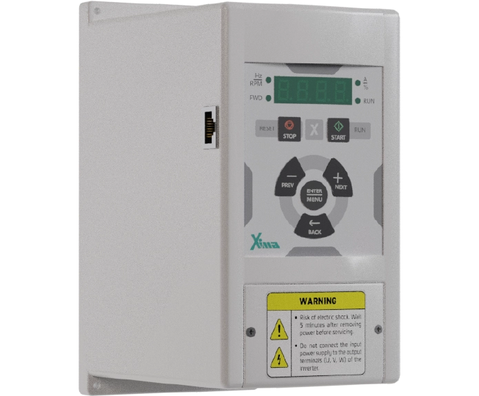
اینورتر 1.1 کیلووات تک فاز سری صنعتی
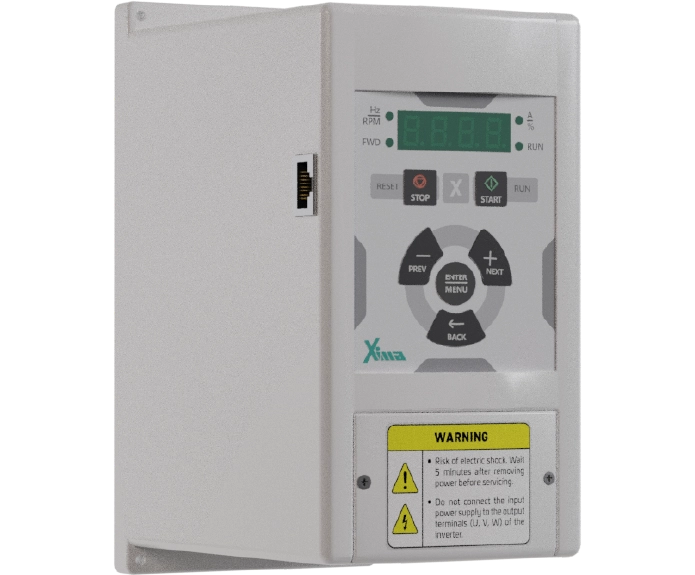
اینورتر 1.5 کیلووات تک فاز سری صنعتی
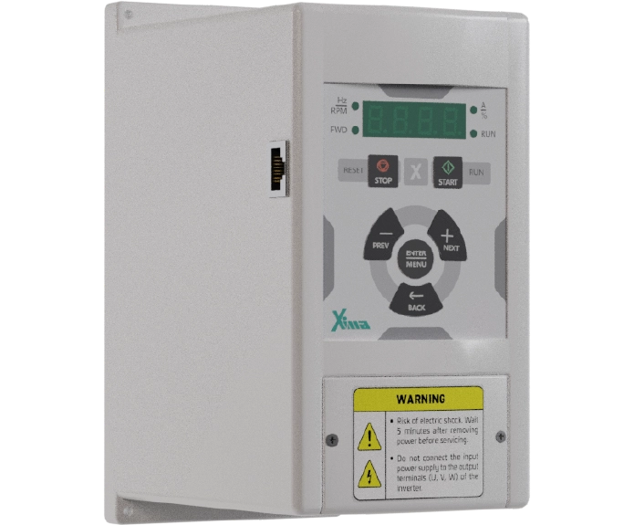
اینورتر 2.2 کیلووات تک فاز سری صنعتی
User Comments
Comments
No comments yet.