کنترل PID اینورتر چیست؟ آموزش تنظیم پارامترهای PID در درایو

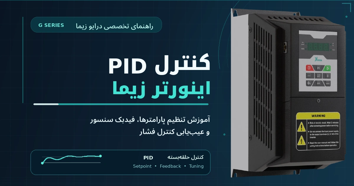
نحوه عملکرد کنترل PID اینورتر؛ از دریافت فیدبک تا تنظیم خودکار سرعت موتور
کنترل PID اینورتر روشی برای تنظیم خودکار سرعت موتور بر اساس اختلاف «مقدار مطلوب فرآیند» و «مقدار اندازهگیریشده» است. برای مثال، اگر فشار یک خط پمپاژ از مقدار هدف کمتر شود، در یک سیستم با جهت کنترل صحیح، اینورتر میتواند با افزایش فرکانس خروجی، دور پمپ را تغییر دهد تا فشار به مقدار مطلوب نزدیک شود. در چنین سیستمی لازم نیست اپراتور برای هر تغییر مصرف، فرکانس موتور را دستی اصلاح کند.
اما فعالکردن PID بهتنهایی برای کنترل درست فشار کافی نیست. مرجع (Setpoint)، منبع فیدبک، محدوده سنسور، جهت کنترل، فرمانهای دارای اولویت و محدودیتهای موتور باید با هم سازگار باشند. در این راهنما ابتدا مفهوم PID را به زبان ساده توضیح میدهیم؛ سپس پارامترهای درایو صنعتی سری G زیما را براساس دفترچه رسمی بررسی میکنیم و دو روش متفاوتِ تعریف مرجع، مثال سنسور فشار ۴ تا ۲۰ میلیآمپر و عیبیابی مشکلات رایج را پیش میبریم.
فهرست مطالب
خلاصه سریع: برای تنظیمات PID اینورتر سری G کدام پارامترها مهماند؟
| کد | وظیفه | نکته کلیدی |
|---|---|---|
SE15 | انتخاب کنترلر | 0 غیرفعال؛ 1 کنترل PID؛ 2 کنترل On/Off |
SE16 | بخش تناسبی P | محدوده 0.01–99.99؛ پیشفرض 1.00 |
SE17 | بخش انتگرالی I | محدوده 0.01–99.99؛ پیشفرض 1.00 |
SE18 | بخش مشتقی D | محدوده 0.01–99.99؛ پیشفرض 1.00 |
SE19 | معکوسسازی فرآیند PID | 0 عادی؛ 1 معکوس؛ نیازمند بررسی رفتار واقعی حلقه |
IO05 | انتخاب منبع مرجع | برای نمونه 0 ورودی V1، و 4 کلیدهای +/- صفحهکلید |
IO15 | انتخاب منبع فیدبک | 1 برای ورودی جریان I1 |
IO06 | نوع بازه جریان I1 | 0 برابر ۰–۲۰ و 1 برابر ۴–۲۰ میلیآمپر |
IO07 | انتهای بالای بازه I1 | برای سنسور نمونه، 20.00 mA |
IO33 | ابتدای بازه جریان I1 | برای سنسور نمونه، 4.00 mA؛ در حالت IO06=1 مؤثر است |
SE22 و SE23 | حالت و مقدار اولیه مرجع PID | کاربرد آنها را باید در کنار منبع مرجع IO05 تفسیر کرد |
IO03 | بازتعریف ورودی D5 | گزینه 4 برای فعالسازی PID از راه D5 در سناریوی مربوط |
نکته مهم: این جدول نقشه راه است، نه فهرست مقادیر آماده برای همه پمپها. مقدار مناسب ضرایب، جهت کنترل، فرکانسهای مجاز و نحوه فرمان Run/Enable به پروژه وابسته است.
کنترل PID اینورتر چیست و چگونه کار میکند؟
PID از سه عبارت Proportional (تناسبی)، Integral (انتگرالی) و Derivative (مشتقی) تشکیل شده است. کنترلر، اختلاف بین مقدار هدف و مقدار واقعی را بررسی میکند و بر مبنای آن فرمان اصلاحی میسازد. در اینورتر، این فرمان میتواند به تغییر فرکانس خروجی و در نتیجه تغییر سرعت موتور منجر شود.
اجزای حلقه کنترل عبارتاند از:
- SP یا Setpoint: مقدار مطلوب؛ مثلاً ۶ بار فشار.
- PV یا Process Variable/Feedback: مقدار واقعی فرآیند که سنسور یا منبع فیدبک گزارش میکند.
- Error: اختلاف مقدار مطلوب و مقدار واقعی.
- Controller: الگوریتمی که بر اساس خطا فرمان اصلاحی تولید میکند.
- Motor + Process: موتور، پمپ یا فن و فرآیندی که تغییر دور روی آن اثر میگذارد.
مسیر عملکرد: مرجع فشار ← مقایسه با فشار اندازهگیریشده ← کنترلر PID ← فرمان فرکانس درایو ← موتور و پمپ ← سنسور فشار ← بازگشت فیدبک به کنترلر.
در کنترل حلقهباز ممکن است فرکانس فرمان روی ۳۵ هرتز باقی بماند، حتی وقتی فشار فرآیند تغییر میکند. در کنترل حلقهبسته PID، درایو بر اساس اختلاف مرجع و فیدبک تلاش میکند اثر تغییر تقاضا را جبران کند. البته این توانایی نامحدود نیست: اگر پمپ ظرفیت کافی نداشته باشد یا خروجی به محدودیت فرکانس رسیده باشد، PID نمیتواند صرفاً با تغییر ضرایب به فشار هدف برسد.
PID فرآیندی با کنترل برداری حلقهبسته موتور تفاوت دارد. کنترل برداری عمدتاً با کنترل سرعت و گشتاور موتور مرتبط است؛ اما در PID فرآیندی، متغیری مثل فشار یا دبی هدف کنترل است و فیدبک آن باید معتبر باشد.
P، I و D دقیقاً چه کاری انجام میدهند؟
| جزء کنترلر | اثر اصلی | پیامد تنظیم نامناسب |
|---|---|---|
| P | واکنش متناسب با خطای لحظهای | بهره زیاد ممکن است نوسان و فراجهش ایجاد کند؛ بهره کم ممکن است پاسخ را کند کند |
| I | کاهش خطای ماندگار با جمعکردن اثر خطا در زمان | اثر شدید ممکن است فراجهش، نوسان و انباشت انتگرال ایجاد کند |
| D | واکنش به نرخ تغییر خطا در پیادهسازی متداول | به نویز فیدبک حساس است و همیشه ضروری نیست |
رابطه آموزشی متداول چنین است:
e(t) = SP(t) − PV(t)
u(t) = Kp × e(t) + Ki × ∫e(t)dt + Kd × de(t)/dt
این فرمول برای فهم منطق PID است؛ نباید از آن نتیجه گرفت که اعداد SE16 تا SE18 دقیقاً همان ضرایب ریاضی با همان واحد و مقیاساند. ساختار پیادهسازی درایو را باید از دفترچه نسخه مربوط و پاسخ واقعی فرآیند شناخت. همچنین جهت خطا در فرآیند معکوس میتواند متفاوت باشد.
در بسیاری از کاربردهای صنعتی ساختار PI کفایت میکند؛ بااینحال، در دفترچه بررسیشده سری G، محدوده SE18 از 0.01 آغاز میشود. بنابراین توصیه عمومی «SE18=0 را وارد کنید تا D حذف شود» برای این نسخه معتبر نیست؛ درباره امکان یا روش غیرفعالسازی جزء مشتقی باید از مستندات و پشتیبانی فنی همان مدل استعلام شود.
قبل از تنظیم PID: پنج بررسی ضروری
۱. موتور و درایو: اطلاعات پلاک موتور، ظرفیت درایو، حالت فرمان، محدوده فرکانس مجاز، زمان شتاب و توقف و حفاظتهای موتور باید قبلاً کنترل شده باشند. ابتدا عملکرد عادی موتور را در شرایط ایمن بررسی کنید.
۲. متغیر فرآیند: روشن کنید دقیقاً چه چیزی کنترل میشود: فشار خروجی، فشار نقطه مصرف، دبی، سطح مخزن یا متغیری دیگر. محل نصب سنسور روی نتیجه کنترل اثر دارد.
۳. مشخصات سنسور: نوع خروجی (۴–۲۰ میلیآمپر، ۰–۲۰ میلیآمپر یا ولتاژ)، بازه اندازهگیری، تغذیه، تعداد سیمها، کالیبراسیون و خطای مجاز را از پلاک و دیتاشیت خود سنسور بخوانید.
۴. فرمان و محدودیتها: شرایط Run و Enable، فرمانهای Preset، حداقل/حداکثر فرکانس و حفاظتهایی مثل جلوگیری از خشککارکردن یا افزایش خطرناک فشار باید پیش از آزمون مشخص باشند.
۵. نسخه دستگاه: مطمئن شوید مدل و نرمافزار دستگاه با دفترچه مورد استناد سازگار است. در این راهنما هیچ مقدار پیشنهادی جای این تطبیق را نمیگیرد.
پارامترهای PID در درایو زیما سری G
۱. فعالسازی کنترلر با SE15
در دفترچه V5.2، مقدار SE15=1 کنترل PID را انتخاب میکند؛ SE15=0 کنترلر را غیرفعال میکند و مقدار 2 به حالت On/Off اختصاص دارد. گزینه دیگری نیز برای فعالسازی از راه ورودی دیجیتال D5 مطرح شده است: در سناریوی تعریفشده در دفترچه، IO03=4 نقش فعالسازی راهدور PID را به D5 میدهد. استفاده از آن به وضعیت ورودی و منطق فرمان پروژه بستگی دارد؛ این روش را بدون بررسی با تنظیم مستقیم SE15 ترکیب نکنید.
اولویت فرمانها را فراموش نکنید: دفترچه هشدار میدهد فعالشدن یکی از ورودیهای Preset میتواند درایو را موقتاً از مد PID خارج کند. پس اگر PID «فعال است» اما خروجی مطابق فیدبک تغییر نمیکند، قبل از دستکاری ضرایب، ورودیهای دیجیتال را بررسی کنید.
۲. انتخاب منبع فیدبک با IO15
مقدار IO15 | منبع فیدبک در نسخه مورد بررسی |
|---|---|
1 | ورودی جریان I1 |
2 | ورودی ولتاژ V2 |
3 | ورودی فرکانسی HSI؛ با محدودیت نقش همزمان HSI |
4 | ارتباط Modbus |
5 | توان تزریقی به موتور |
برای یک ترنسمیتر فشار سازگار با خروجی ۴–۲۰ میلیآمپر که از ورودی I1 استفاده میکند، IO15=1 انتخاب متناظر است. انتخاب این پارامتر به معنای تأیید سیمبندی نیست؛ نقشه اتصال و تغذیه سنسور باید جداگانه بررسی شوند.
۳. مقیاسبندی صحیح جریان I1 با IO06، IO07 و IO33
انتخاب ورودی درست کافی نیست؛ فیدبک باید درست به درصد تبدیل شود. در نسخه مورد بررسی:
IO06=0برای سنسور با محدوده ۰ تا ۲۰ میلیآمپر است.IO06=1برای سنسور با محدوده ۴ تا ۲۰ میلیآمپر است.IO07مقدار انتهای بالای محدوده جریان I1 را مشخص میکند؛ برای مثال معمول20.00 mA.IO33پارامتر I1 Current Range Minimum Value است؛ در مثال ۴–۲۰ میلیآمپر مقدار4.00 mAدارد و براساس متن دفترچه، در حالتIO06=1اثرگذار است.
بنابراین برای ترنسمیتر خطی ۴–۲۰ میلیآمپر با بازه فشار صفر تا ۱۰ بار، در صورت سازگاری کامل دستگاه و سنسور، ۴ میلیآمپر باید معادل صفر درصد و ۲۰ میلیآمپر معادل صد درصد فیدبک باشد. به همین دلیل است که اضافهکردن IO33 به آموزش اهمیت دارد.
اگر ترنسمیتر از ابتدا یا انتهای متفاوتی استفاده میکند، صرفاً از روی این مثال مقدار پارامترها را کپی نکنید. کالیبراسیون واقعی، محدوده قابل تنظیم و رفتار در قطع سیگنال باید بررسی شوند.
۴. انتخاب مرجع با IO05؛ تفاوت آن با SE22 و SE23
یکی از اشتباههای رایج این است که «منبع مرجع» و «مقدار اولیه مرجع» یک چیز فرض شوند. در زیما سری G، IO05 انتخاب میکند فرمان مرجع از کجا دریافت شود؛ SE22 و SE23 به تنظیم مقدار اولیه مرجع PID مربوطاند.
از گزینههای مستند IO05 میتوان به 0 برای ورودی ولتاژ V1، 2 برای جریان I1، 4 برای کلیدهای +/- صفحهکلید، 6 برای Modbus و 7 برای حالت پلهای صفحهکلید اشاره کرد. جدول کامل گزینهها را در دفترچه مدل دستگاه ببینید.
مقادیر SE22 عبارتاند از:
0: شروع با مرجع صفر.1: شروع با آخرین مقدار ذخیرهشده پیش از خاموشی.2: شروع با مقدار تعریفشده درSE23.
SE23 مقدار اولیه مرجع را درصدی تعیین میکند. برای نمونه، اگر روش مرجع صفحهکلید IO05=4 انتخاب شود، حالت SE22=2 میتواند مقدار اولیه تعیینشده در SE23 را مبنا قرار دهد؛ سپس رفتار کلیدهای تغییر مرجع نیز باید در نظر گرفته شود. اما اگر مرجع از V1 میآید، عدد SE23 را بدون بررسی رفتار ورودی آنالوگ، جایگزین ولتاژ واقعی V1 فرض نکنید.
تفاوت نگارشی در دفترچه: بازه عددی SE23 در جدول پارامترهای اصلی و جدول خلاصه PID یکسان ثبت نشده است. مقدار 60% نمونه این مقاله داخل هر دو بازه قرار میگیرد؛ برای تنظیم نزدیک مرزها، نمایش و محدوده نسخه نصبشده را مبنا قرار دهید. همچنین جدول جامع IO05 و خلاصه PID درباره تعداد گزینهها/مقدار پیشفرض کاملاً یکسان نیستند؛ از روی جدول خلاصه، مقدار کارخانه را قطعی فرض نکنید.
۵. جهت عملکرد فرآیند و نقش SE19
با کاهش فشار در سیستم پمپاژ متداول، معمولاً لازم است سرعت پمپ افزایش یابد؛ اما منطق کنترل در تمام فرآیندها یکسان نیست. در دفترچه، SE19 با عنوان PID Process Reverse معرفی شده و برای رفتار معکوس فرآیند تعریف شده است. توضیح سازنده تنها به جابهجایی ساده دو علامت محدود نمیشود و به نسبت معکوس فیدبک و کمیت کنترلشونده هم اشاره دارد.
پس اگر فشار کم میشود و فرکانس نیز برخلاف انتظار کاهش مییابد، بلافاصله SE19 را تغییر ندهید. ابتدا مطمئن شوید علامت و مقیاس سیگنال درست است، مرجع از ورودی صحیح میآید، ورودیهای Preset فعال نیستند و اندازهگیری سنسور با فشارسنج مرجع مطابقت دارد. سپس رفتار حلقه و تنظیم معکوسسازی باید در شرایط ایمن و تحت نظارت فنی ارزیابی شود.
مثال کامل: کنترل فشار ۶ بار با ترنسمیتر ۴–۲۰ میلیآمپر
فرض کنیم یک پمپ و درایو سری G داریم و ترنسمیتر فشار خطی با مشخصات زیر نصب شده است. این مثال برای آموزش مقیاس و انتخاب منبع است؛ داده واقعی یک پروژه راهاندازیشده نیست.
| مشخصه | مقدار در مثال |
|---|---|
| محدوده سنسور فشار | 0–10 bar |
| خروجی ترنسمیتر | 4–20 mA |
| فشار هدف | 6 bar |
| ورودی فیدبک | I1 |
| درصد متناظر با فشار هدف | 60% |
| جریان مورد انتظار سنسور در ۶ بار | 13.6 mA |
محاسبه Setpoint و فیدبک
برای بازه صفر تا ۱۰ بار:
Setpoint (%) = (6 ÷ 10) × 100 = 60%
برای ترنسمیتر خطی ۴–۲۰ میلیآمپر:
I(mA) = 4 + [(P − Pmin) ÷ (Pmax − Pmin)] × 16
در فشار ۶ بار:
I = 4 + (6 ÷ 10) × 16 = 13.6 mA
بنابراین اگر سنسور سالم، کالیبره و بهدرستی مقیاسبندی شده باشد، در ۶ بار واقعی باید جریان خروجی آن حدود ۱۳٫۶ میلیآمپر باشد؛ این عدد یک نقطه کنترل برای بررسی مقیاس است، نه تضمین دقت سنسور.
اگر همان فشار ۶ بار را با سنسور ۰ تا ۱۶ بار اندازه بگیریم، مرجع متناسب به ۳۷٫۵ درصد و جریان مورد انتظار به ۱۰ میلیآمپر تغییر میکند. پس مقدار درصدی بدون ذکر بازه سنسور معنای فنی کاملی ندارد.
روش A: مرجع فشار از ورودی V1؛ مطابق ایده مثال رسمی زیما
نقشهای پارامترها در این مسیر عبارتاند از:
| پارامتر | نقش و مقدار آموزشی |
|---|---|
IO05=0 | دریافت مرجع از V1 |
IO15=1 | دریافت فیدبک از I1 |
IO06=1 | انتخاب بازه ۴–۲۰ میلیآمپر |
IO07=20.00 mA | انتهای بالای جریان ورودی I1 |
IO33=4.00 mA | ابتدای جریان ورودی I1 |
SE15=1 | فعالسازی کنترل PID |
SE16، SE17، SE18 | نیازمند تنظیم بر اساس پاسخ سیستم؛ مقدار آماده پیشنهاد نمیشود |
اگر V1 واقعاً به بازه ۰ تا ۱۰ ولت مقیاس شده باشد، مرجع معادل ۶۰ درصد برابر با ۶ ولت روی V1 است. این یک تبدیل ریاضی برای توضیح مرجع است؛ پیش از اجرا باید محدوده واقعی V1، نحوه تولید ولتاژ و پارامترهای مقیاس ولتاژ مانند IO08 بررسی شوند.
روش B: مرجع اولیه ۶۰ درصد از صفحهکلید
اگر در سناریوی دیگری بخواهیم مرجع اولیه از روش صفحهکلید تعیین شود، ترکیب پارامترها میتواند چنین باشد:
| پارامتر | مقدار یا توضیح |
|---|---|
IO05=4 | انتخاب کلیدهای +/- صفحهکلید بهعنوان روش تعیین مرجع |
SE22=2 | شروع با مقدار ثبتشده در SE23 |
SE23=60% | مرجع اولیه متناسب با ۶ بار، فقط برای سنسور ۰–۱۰ بار |
IO15=1 | فیدبک از I1 |
IO06=1، IO07=20.00، IO33=4.00 | مقیاس جریان سنسور |
SE15=1 | فعالسازی PID |
در این روش، SE23=60% جایگزین انتخاب منبع مرجع نمیشود. کلیدهای صفحهکلید و منطق نگهداری مقدار مرجع در رفتار واقعی دستگاه دخیلاند. این جدول عمداً با روش A یکی نشده است؛ یکی از V1 استفاده میکند و دیگری از صفحهکلید.
چطور صحت مثال را بدون حدسزدن بررسی کنیم؟
در یک آزمایش طراحیشده و ایمن، مسئول فنی باید این موارد را ثبت و با هم مقایسه کند:
- فشار واقعی اندازهگیریشده با گیج/ابزار مرجع و فشار اعلامشده از ترنسمیتر؛
- جریان سنسور و درصد فیدبک خواندهشده درایو؛
- مقدار مرجع واقعی دستگاه، نه صرفاً عدد واردشده در یک پارامتر؛
- وضعیت فرمانهای Run/Enable و ورودیهای Preset؛
- فرکانس خروجی و محدوده مجاز آن؛
- وضعیت پایدار، میزان فراجهش و روند فشار در تغییر محدود تقاضای کنترلشده.
در سری G گزینههای نمایش روی پنل نیز وجود دارند؛ مثلاً IO10 میتواند برای مشاهده درصد متغیر کنترلی/فیدبک، طبق دفترچه و وضعیت نمایشی دستگاه، بهکار رود. این مشاهده فقط یک ابزار پایش است و جای مانومتر مستقل را نمیگیرد.
روش اصولی تنظیم ضرایب PID و کاهش نوسان
هیچ ترکیب عددی P، I و D برای همه پمپها مناسب نیست. اگر سیگنال فیدبک غلط باشد یا پمپ در محدوده کار مجاز قادر به تأمین فشار هدف نباشد، تغییر مداوم ضرایب معمولاً مشکل را حل نمیکند.
گام اول — کیفیت اندازهگیری: وقتی فشار واقعی ثابت است، سیگنال سنسور نباید بیدلیل پرش شدید داشته باشد. محل نصب سنسور، نویز الکتریکی، مشترک سیگنال، کالیبراسیون و نوسانات واقعی فشار را از هم تفکیک کنید.
گام دوم — علامت عملکرد: با تغییر محدود و مجاز شرایط، بررسی کنید تغییر فرکانس، متغیر فرآیند را در جهت مورد انتظار تغییر میدهد یا نه. درباره SE19 با حدس تصمیم نگیرید.
گام سوم — محدودیت و ظرفیت: پیش از تنظیم P و I مشخص کنید خروجی درایو به حداقل یا حداکثر فرکانس نچسبیده و پمپ ظرفیت فرآیندی کافی دارد.
گام چهارم — اثر P: در تست کنترلشده، تغییرات کوچک و ثبتشده در SE16 و اثر آن بر سرعت پاسخ و نوسان بررسی میشود. افزایش بیرویه ممکن است باعث رفتوبرگشت خروجی شود.
گام پنجم — اثر I: SE17 در کاهش خطای ماندگار مؤثر است، اما واکنش انتگرالی شدید میتواند فراجهش را افزایش دهد؛ بهخصوص وقتی خروجی برای مدتی به حد مجاز رسیده است.
گام ششم — نقش D و نویز: SE18 تنها در صورتی بررسی شود که ماهیت فرآیند و کیفیت فیدبک این کار را توجیه کند. محدوده مجاز این پارامتر در دفترچه V5.2 از 0.01 آغاز میشود و نباید عدد صفر یا یک روش غیرفعالسازی اثباتنشده پیشنهاد کرد.
گام هفتم — آزمون تکرارپذیر: شرایط آزمون، فشار هدف، مقدار واقعی، فرکانس، ضرایب و نتیجه هر تغییر را ثبت کنید. صرف اینکه فشار یک بار به عدد هدف برسد، به معنای پایداری حلقه نیست.
عیبیابی PID درایو زیما: از علامت تا اقدام
| علامت مشاهدهشده | نخستین بررسی کمریسک | علتهای محتمل و مسیر بعدی |
|---|---|---|
| PID انتخاب شده ولی فرکانس تقریباً ثابت است | مقدار واقعی مرجع و فیدبک، IO05 و IO15 را بخوانید | یکسانبودن منبع مرجع و فیدبک، فعالبودن Preset، محدودیت فرکانس یا نبود تغییر واقعی در خطا |
| فشار کمتر از هدف است، ولی دور زیاد نمیشود | فشار گیج، درصد فیدبک و وضعیت Run/Enable را مقایسه کنید | جهت/مقیاس نادرست، فرمان دارای اولویت، سقف مجاز یا ظرفیت ناکافی |
| فیدبک در حالت ثابت پرشهای تند دارد | مقدار سنسور را با ابزار مرجع مقایسه کنید | نویز، سیمبندی، جای نامناسب سنسور، کالیبراسیون یا تغییر واقعی فشار |
| فشار بهآرامی بالا و پایین میرود | روند همزمان فشار و فرکانس را ثبت کنید | تنظیم نامناسب P/I، تأخیر فرآیند، رمپ یا رفتار هیدرولیکی سیستم |
| فشار بیش از حد از هدف عبور میکند | روند خطا و رسیدن به محدودیت خروجی را بررسی کنید | بهره نامتناسب، اثر زیاد انتگرال، تأخیر سیستم یا مشکل مکانیکی |
| فشار به Setpoint نمیرسد | حد فرکانس، ظرفیت پمپ، نشتی/مقاومت مسیر و جهت چرخش را بررسی کنید | محدودیت فیزیکی فرآیند؛ افزایش ضرایب لزوماً مفید نیست |
| نمایش درصد فیدبک با فشار واقعی نمیخواند | IO06، IO07، IO33 و بازه سنسور را بررسی کنید | مقیاس اشتباه یا سنسور خارج از کالیبراسیون |
| بعد از تغییر ضرایب هیچ تغییری دیده نمیشود | فعالبودن حقیقی PID و ورودیهای Preset را بررسی کنید | مد کنترلی دیگر یا منبع فرمان اشتباه فعال است |
| پس از قطع سنسور رفتار خطرناک مشاهده میشود | سیستم را طبق رویه ایمن پروژه از مدار بهرهبرداری خارج کنید | فقدان حفاظت مستقل یا سناریوی مدیریت خرابی فیدبک؛ به PID بهتنهایی تکیه نشود |
| در مصرف کم، پمپ پیوسته تغییر دور دارد | رفتار مخزن فشار، حداقل دبی پمپ و حداقل دور را بررسی کنید | مشکل طراحی هیدرولیکی یا ضرورت منطق کنترلی مکمل، نه صرفاً تغییر PID |
چرا یکسانبودن منبع مرجع و فیدبک مهم است؟
دفترچه رسمی هشدار میدهد اگر منبع ورودیِ مرجع و فیدبک یکی تعریف شوند، موتور ممکن است روی فرکانس ثابتی بماند. برای همین، ترکیب IO05 و IO15 یکی از اولین کنترلهای عیبیابی است. در روش A این راهنما، مرجع از V1 و فیدبک از I1 گرفته میشود؛ بنابراین نقشهایشان جداست.
چرا با فعالشدن Preset کنترل PID قطع میشود؟
طبق دفترچه، ورودیهای Preset اولویت بالاتری دارند و میتوانند کنترل PID را تا زمان غیرفعالشدن ورودی مربوط کنار بزنند. بههمین دلیل، بیاثرشدن تغییر P و I همیشه نشانه خرابی درایو یا الگوریتم PID نیست.
آیا نوسان فشار همیشه از ضرایب PID است؟
خیر. نویز سنسور، محل نصب ترنسمیتر، مخزن دیافراگمی، شیر یکطرفه، تغییر تقاضا، محدودیت پمپ و رمپ میتوانند نقش داشته باشند. ابتدا اندازهگیری و فرآیند را از رفتار کنترلر جدا کنید، سپس ضرایب را بررسی کنید.
کاربردهای PID اینورتر و محدودیتهای آن
کنترل فشار پمپ: تغییر سرعت میتواند فشار را نسبت به تغییر مصرف تنظیم کند؛ به شرطی که پمپ ظرفیت کافی، سنسور درست و حفاظت مناسب داشته باشد. برای انتخاب تجهیز، راهنمای اینورتر پمپ آب زیما و برای مدار فرمان، نقشه راهاندازی بوسترپمپ با اینورتر را نیز ببینید.
کنترل دبی و سطح: در صورت وجود سنسور مناسب و ارتباط قابل کنترل بین سرعت پمپ و متغیر اندازهگیریشده، PID میتواند بخشی از راهکار باشد. جلوگیری از خشککارکردن و سرریز باید مستقل بررسی شود.
کنترل دما: در سامانههایی که تغییر دور فن یا پمپ گردش واقعاً بر دما اثر دارد، میتوان از حلقه فرآیندی استفاده کرد؛ اما تأخیر حرارتی و جهت عملکرد باید ارزیابی شود.
کنترل کشش مواد: در رولپیچها و خطوط تولید، کشش میتواند به فیدبک سرعت/گشتاور وابسته باشد؛ این کاربرد به طراحی مکانیکی و کنترلی اختصاصی نیاز دارد.
تفاوت PID با کنترل On/Off در اینورتر
در PID، خروجی کنترلی با توجه به خطا تغییر میکند. در On/Off، تصمیم کنترلی عمدتاً میان حالتهای گسسته و آستانههای تعریفشده انجام میشود. سری G این دو روش را در SE15 تفکیک کرده است: 1 برای PID و 2 برای On/Off. انتخاب مناسب به دینامیک، دقت و الزامات فرآیند بستگی دارد؛ PID در همه کاربردها بهترین انتخاب نیست.
PID داخلی درایو بهتر است یا PID در PLC؟
اگر فقط یک حلقه کنترلی ساده نیاز باشد، PID داخلی درایو میتواند نیاز به پیادهسازی همان حلقه در PLC را کاهش دهد. در فرآیندهای چندمتغیره، توالیهای پیچیده یا هماهنگی چند پمپ، کنترلر مرکزی یا PLC ممکن است مناسبتر باشد. دو کنترلر مستقل نباید بدون طراحی مشخص، همزمان برای یک فرمان فرکانس تصمیمهای متناقض بگیرند. برای بررسی ارتباطات، آموزش اتصال اینورتر به PLC با Modbus RTU مکمل این بحث است.
نکات ایمنی که نباید به PID واگذار شوند
- نصب، سیمبندی و تغییرات مرتبط با برق قدرت و مدار فرمان باید فقط توسط فرد صلاحیتدار و مطابق دستورالعمل سازنده انجام شود. پیش از دسترسی به بخشهای برقی، ایزولهسازی، زمان تخلیه و تأیید نبود ولتاژ خطرناک ضروری است.
- تغذیه ترنسمیتر را حدس نزنید. نقشه نمونه رسمی، نوع خاصی از اتصال را نشان میدهد؛ ولتاژ و نوع سنسور نصبشده باید مستقلاً تأیید شود.
- محدودیتهای فشار، دور، دبی، جریان موتور و شرایط کار خشک را براساس مشخصات پروژه تعیین کنید.
- قطع فیدبک، اتصال اشتباه، خروج سنسور از بازه و گیرکردن خروجی روی حد مجاز، باید در تحلیل خطر پروژه دیده شوند.
- PID جایگزین شیر اطمینان، حفاظت مستقل اضافهفشار، حفاظت خشککارکردن، توقف اضطراری یا دیگر تجهیزات ایمنی لازم نیست.
- پس از نهاییشدن کار، مدل، نسخه نرمافزار، شماره پارامترهای تغییرکرده، تاریخ و نتایج تست را ثبت کنید.
سؤالات متداول درباره کنترل PID اینورتر زیما
پارامتر فعالسازی PID در زیما سری G چیست؟
طبق دفترچه V5.2، SE15=1 حالت PID را انتخاب میکند. روش فعالسازی از طریق ورودی دیجیتال D5 نیز در شرایط تعریفشده دفترچه وجود دارد.
برای سنسور فشار ۴–۲۰ میلیآمپر چه پارامترهایی را بررسی کنیم؟
در سناریوی فیدبک I1، IO15=1، IO06=1، IO07 برای انتهای بالای جریان و IO33 برای ابتدای محدوده بررسی میشوند. مشخصات سنسور و سیمبندی واقعی تعیینکننده نهاییاند.
IO05 و IO15 چه تفاوتی دارند؟
IO05 منبع مرجع را انتخاب میکند، در حالی که IO15 منبع فیدبک را تعیین میکند. اشتباهگرفتن آنها از دلایل مهم عملکرد نامطلوب PID است.
تفاوت SE22 و SE23 با IO05 چیست؟
IO05 مشخص میکند مرجع از کجا میآید؛ SE22 حالت مقدار اولیه مرجع PID و SE23 مقدار درصدی آن را تعیین میکنند. کاربردشان باید متناسب با روش واقعی مرجع باشد.
مقدار ۶ بار برای سنسور ۰ تا ۱۰ بار چند درصد و چند میلیآمپر است؟
برای سنسور خطی ۴–۲۰ میلیآمپر، ۶ بار معادل ۶۰ درصد از بازه و ۱۳٫۶ میلیآمپر است. اگر محدوده سنسور تغییر کند، محاسبه نیز تغییر میکند.
آیا برای حذف D باید SE18=0 بگذاریم؟
چنین توصیهای برای دفترچه V5.2 معتبر نیست، چون بازه درجشده برای SE18 از 0.01 شروع میشود. روش احتمالی استفاده از ساختار PI باید برای نسخه واقعی دستگاه تأیید شود.
چرا PID فعال است ولی فرکانس تغییر نمیکند؟
احتمال دارد منبع مرجع و فیدبک درست تعیین نشده باشد، یکی از ورودیهای Preset فعال باشد، فرمان Run/Enable برقرار نباشد یا محدودیتهای خروجی و ظرفیت فرآیند مانع پاسخ شوند.
آیا PID همیشه مصرف برق را کاهش میدهد؟
خیر. در بارهایی مانند برخی پمپها و فنها، کاهش سرعت متناسب با تقاضا ممکن است مصرف انرژی را کم کند؛ میزان واقعی به نقطه کار، راندمان و شرایط بهرهبرداری وابسته است و باید اندازهگیری شود.
آیا میتوان همین کدها را روی دیگر سریهای زیما اعمال کرد؟
خیر. این مقاله مشخصاً به سری G و نسخه دفترچه ذکرشده مربوط است. برای سریهای دیگر، نقشه و پارامترهای همان مدل ملاک است.
جمعبندی: مسیر درست تنظیم PID در سری G زیما
برای تنظیم PID اینورتر زیما، ابتدا نوع متغیر و سنسور را مشخص کنید؛ سپس منبع مرجع IO05 و منبع فیدبک IO15 را جداگانه انتخاب و مقیاس جریان را با IO06، IO07 و IO33 تطبیق دهید. بعد از تعیین حالت کنترلر با SE15، وضعیت ورودیهای Preset و Run/Enable، جهت عملکرد فرآیند و محدودیت فرکانس را کنترل کنید و تازه پس از آن سراغ بهینهسازی تدریجی ضرایب SE16 تا SE18 بروید.
اگر کاربرد شما کنترل فشار پمپ است، دو مسیر این مقاله را با هم اشتباه نگیرید: مرجع آنالوگ V1 مطابق ایده شکل رسمی دفترچه، و مرجع اولیه از صفحهکلید با منطق SE22 و SE23. در هر دو روش، صحت فشار واقعی باید با ابزار مستقل و در شرایط ایمن تأیید شود.
برای انتخاب مدل متناسب با بار و دریافت مستندات، به صفحه محصولات زیما و بخش دانلود راهنماها مراجعه کنید. اگر میان نوع ترنسمیتر، مدل درایو و منطق فرمان پروژه تردید دارید، پیش از راهاندازی از مسیر تماس با کارشناسان زیما مشخصات دستگاه و سنسور را برای بررسی فنی ارائه دهید.
How PID Control in a VFD Turns Sensor Feedback into Automatic Speed Adjustment
PID control in a variable frequency drive (VFD) automatically adjusts motor speed in response to the difference between a desired process value and the value measured by a sensor. In a pressure-controlled pumping system, for example, increased water demand may cause the measured pressure to fall. If the control loop is configured correctly, the VFD can increase pump speed to bring pressure back toward the setpoint.
This means an operator does not have to change the output frequency every time demand changes. But enabling the PID function alone is not enough. The setpoint source, feedback input, sensor scaling, control direction, command priorities and operating limits all need to be configured consistently.
This guide first explains how PID works in a VFD. It then walks through the documented PID parameters of the XIMA Industrial G Series, two different approaches to choosing a setpoint, an example using a 4–20 mA pressure transmitter, and practical troubleshooting checks.
Scope and version: The control principles are broadly relevant to VFDs that support process PID. However, the parameter codes and model-specific examples in this article refer to the XIMA Industrial G Series Installation Manual, version V5.2, firmware H3.24. Do not assume the same parameter codes apply to other XIMA drive series, hardware revisions or firmware versions. For the G Series product family and technical documentation, see the verified Industrial G Series overview and XIMA documentation and downloads.
PID Settings in the XIMA G Series: Quick Parameter Reference
If you are familiar with PID theory and need to locate a setting, start here. These codes relate to the manual version stated above; the values shown are not a universal commissioning recipe.
| Code | Function and settings |
|---|---|
| SE15 | Function: Controller selection Important detail: 0 = Disabled; 1 = PID; 2 = On/Off |
| SE16 | Function: Proportional (P) setting Important detail: Range: 0.01–99.99; default: 1.00 |
| SE17 | Function: Integral (I) setting Important detail: Range: 0.01–99.99; default: 1.00 |
| SE18 | Function: Derivative (D) setting Important detail: Range: 0.01–99.99; default: 1.00 |
| SE19 | Function: PID process reverse Important detail: 0 = Normal; 1 = Reverse; verify the required response |
| IO05 | Function: Setpoint/reference source Important detail: Examples: 0 = V1; 4 = keypad +/- keys |
| IO15 | Function: PID feedback source Important detail: 1 = current input I1 |
| IO06 | Function: I1 current-input range Important detail: 0 = 0–20 mA; 1 = 4–20 mA |
| IO07 | Function: I1 upper current limit Important detail: 20.00 mA in the example |
| IO33 | Function: I1 lower current limit Important detail: 4.00 mA in the example; relevant when IO06 = 1 |
| SE22 / SE23 | Function: Initial PID setpoint mode/value Important detail: Interpret alongside the reference source selected by IO05 |
| IO03 | Function: D5 input function Important detail: Option 4 is associated with PID activation via D5 in the documented configuration |
Do not copy the defaults as recommended tuning values. The correct response direction, frequency limits, run/enable commands and control settings depend on the actual machine and process.
What Is PID Control in a VFD, and How Does It Work?
PID stands for Proportional, Integral and Derivative. A PID controller uses the difference between a desired process value and a measured value to calculate a corrective output. In a VFD, that output can be used to adjust the frequency supplied to the motor, and therefore its speed.
A basic closed-loop system has five elements:
- Setpoint (SP): the required process value, such as 6 bar.
- Process variable (PV) or feedback: the value reported by a sensor or another supported feedback source.
- Control error: the difference between SP and PV.
- PID controller: the algorithm that calculates the corrective command.
- Motor and process: the drive, motor, pump, fan or other equipment that responds to the command.
Control loop: Setpoint → comparison with feedback → PID controller → VFD output-frequency command → motor and process → sensor → feedback to the controller.
With open-loop control, a drive might be instructed to run at 35 Hz regardless of whether process pressure changes. With closed-loop PID control, the frequency command can change as the measured process variable moves away from the target. The controller is still subject to the motor, drive and process limits: no amount of tuning can make an undersized pump produce pressure or flow beyond its capability.
Process PID is not the same as closed-loop vector motor control. Vector control is primarily concerned with motor speed and torque performance. Process PID is used to regulate a process variable such as pressure, flow or temperature using suitable feedback.
What Do the P, I and D Terms Actually Do?
| Term | Role and tuning considerations |
|---|---|
| Proportional (P) | Main purpose: Responds to the current error Possible consequence of poor tuning: Too much action can cause overshoot or oscillation; too little can produce a sluggish response |
| Integral (I) | Main purpose: Reduces persistent steady-state error by accumulating error over time Possible consequence of poor tuning: Excessive integral action can increase overshoot, hunting and integral windup |
| Derivative (D) | Main purpose: Responds to how quickly the error changes in a conventional PID implementation Possible consequence of poor tuning: Can amplify the effects of noisy measurement signals |
A commonly used continuous-time representation is:
e(t) = SP(t) − PV(t)
u(t) = Kp × e(t) + Ki × ∫e(t)dt + Kd × de(t)/dt
This equation explains the principle; it does not establish that XIMA settings SE16, SE17 and SE18 map directly to these mathematical coefficients with identical units or scaling. Actual controller implementations vary. The process direction may also require a different treatment of control error.
Many industrial processes operate satisfactorily with PI control alone. However, the documented valid range for SE18 begins at 0.01 in the manual version used here. Therefore, do not assume that entering SE18 = 0 is an acceptable way to disable derivative action. Confirm the supported method for the installed drive and firmware.
Before You Configure PID: Five Essential Checks
1. Motor and drive: Confirm the motor nameplate data, drive rating, operating mode, acceleration/deceleration settings, permitted frequency range and motor protection. Make sure the motor operates correctly in an appropriate non-PID test before attempting closed-loop operation.
2. Process variable: Decide exactly what you need to regulate: pump discharge pressure, pressure at a remote point of use, flow rate, tank level or another measurable quantity. Sensor placement can change how the control loop behaves.
3. Sensor specifications: Check whether the transmitter provides 4–20 mA, 0–20 mA or a voltage output. Confirm its measurement span, supply requirements, wiring arrangement, accuracy and calibration from its own datasheet.
4. Commands and limits: Review Run and Enable conditions, preset-frequency inputs, minimum and maximum frequency, and independent process protection such as dry-run and overpressure safeguards.
5. Hardware and firmware version: Match the drive model and software version to the correct manual. Parameter codes should not be transferred blindly between product series.
How to Configure PID Parameters on a XIMA Industrial G Series Drive
Step 1: Select the Controller with SE15
In the referenced G Series manual, SE15 = 1 selects PID control. SE15 = 0 disables the controller, while SE15 = 2 selects On/Off control.
The manual also describes a configuration in which digital input D5 can be used to enable PID operation. In that arrangement, IO03 = 4 assigns the corresponding function to D5. Whether this approach is appropriate depends on the input wiring and the installation’s command logic; it should not be mixed with another control arrangement without verifying how priority and enable conditions work.
Check preset-frequency inputs. An active preset command can temporarily override PID operation. If the drive is running but its output does not respond to the process variable, inspect digital-input states before changing the P, I or D values.
Step 2: Choose the Feedback Source with IO15
| IO15 value | Feedback source |
|---|---|
| 1 | I1 current input |
| 2 | V2 voltage input |
| 3 | HSI high-speed frequency input, subject to its assigned function |
| 4 | Modbus |
| 5 | Power delivered to the motor |
For a compatible 4–20 mA pressure transmitter connected to I1, the corresponding choice is IO15 = 1. Selecting the input in software does not verify the physical wiring. Check transmitter supply voltage, signal return, terminal allocation and the drive’s wiring diagram separately.
Step 3: Scale the I1 Feedback Signal with IO06, IO07 and IO33
Even a correctly selected input will give misleading feedback if the current range is scaled incorrectly. In the documented G Series version:
IO06 = 0selects a 0–20 mA current range.IO06 = 1selects a 4–20 mA current range.IO07defines the upper end of the I1 current range;20.00 mAis used in the example.IO33defines the I1 current-range minimum;4.00 mAis used here, and the manual specifies its relevance whenIO06 = 1.
For a linear 0–10 bar transmitter with a 4–20 mA output, 4 mA should represent 0% of the measurement span and 20 mA should represent 100%, provided the sensor and input are scaled as intended. Do not reuse these settings for a sensor with a different range without checking calibration and the drive’s response to a lost signal.
Step 4: Set the Reference Source with IO05 — and Understand SE22 and SE23
The reference source is not the same thing as the initial reference value. On the XIMA G Series, IO05 determines where the reference command comes from. SE22 and SE23 determine the initial PID setpoint behavior.
Documented IO05 options include 0 = V1 voltage input, 2 = I1 current input, 4 = keypad +/- keys, 6 = Modbus and 7 = stepped keypad mode. Consult the full parameter table for the complete set.
SE22 defines the initial-setpoint mode:
SE22 = 0: begin with a zero reference.SE22 = 1: begin with the last stored reference before shutdown.SE22 = 2: begin with the value specified by SE23.
SE23 defines the initial reference as a percentage. For example, with keypad-based reference selection (IO05 = 4), SE22 = 2 can establish the initial reference from SE23, subject to the keypad control logic. If the reference instead comes from V1, do not assume that entering a value in SE23 replaces the actual analog voltage at V1.
Documentation discrepancy: The referenced manual does not present the same SE23 numeric range in its main parameter table and PID summary table. The 60% example below falls within both stated ranges. For values near the documented limits, check the installed firmware and its actual parameter range. Some IO05 details also differ between the complete table and the abbreviated PID section, so do not infer factory defaults from the short summary alone.
Step 5: Verify the Control Direction and SE19
In a typical pressure-boosting system, falling pressure calls for increased pump speed. Other processes can behave in the opposite direction. The G Series manual identifies SE19 as PID Process Reverse, with normal and reverse modes.
If pressure falls but motor speed also falls when it should rise, do not immediately toggle SE19. First verify the sensor reading, the signal scaling, the selected reference source, the absence of overriding preset commands, and agreement with an independent pressure gauge. Only then assess the required control direction under safe, supervised test conditions.
Worked Example: Holding 6 bar with a 4–20 mA Pressure Transmitter
Consider a hypothetical pumping system using a XIMA Industrial G Series drive and a linear pressure transmitter. This example demonstrates signal scaling and reference selection; it is not a tested configuration for a specific installation.
| Item | Example value |
|---|---|
| Pressure measurement range | 0–10 bar |
| Transmitter output | 4–20 mA |
| Desired pressure | 6 bar |
| Feedback input | I1 |
| Setpoint as a percentage of the sensor span | 60% |
| Expected transmitter signal at 6 bar | 13.6 mA |
Calculate the Percentage Setpoint and Feedback Current
For a 0–10 bar transmitter, a 6 bar target represents:
Setpoint (%) = (6 ÷ 10) × 100 = 60%
For a linear 4–20 mA transmitter, the output current can be estimated from:
I (mA) = 4 + [(Pressure − Pmin) ÷ (Pmax − Pmin)] × 16
At 6 bar:
I = 4 + (6 ÷ 10) × 16 = 13.6 mA
When the actual process pressure is 6 bar, a healthy and correctly calibrated transmitter should therefore output approximately 13.6 mA. This is an expected scaling check, not a guarantee of instrument accuracy.
If the sensor range changes to 0–16 bar, the same 6 bar target becomes 37.5% of span, and the expected current becomes 10 mA. A percentage setpoint is meaningless unless the associated measurement range is known.
Method A: Analog Setpoint from V1, with Pressure Feedback on I1
The manufacturer’s pressure-control example in Figure 74, printed page 153 of the G Series V5.2 manual, illustrates an analog voltage reference through V1 and a current-based pressure feedback signal through I1. The relevant settings to review are:
| Parameter | Role in this example |
|---|---|
| IO05 = 0 | Reference source: V1 |
| IO15 = 1 | Feedback source: I1 |
| IO06 = 1 | 4–20 mA current range |
| IO07 = 20.00 mA | Upper I1 current limit |
| IO33 = 4.00 mA | Lower I1 current limit |
| SE15 = 1 | PID controller selected |
| SE16 / SE17 / SE18 | Tune from actual process response; no universal values are recommended |
If V1 has been configured as a 0–10 V reference and the mapping is linear, 60% corresponds mathematically to 6 V at V1. Confirm the installed drive’s V1 scaling (including relevant voltage-range settings such as IO08), the reference signal source, and the commissioning documentation before making that assumption on real equipment.
For the manufacturer’s drawing and terminal details, open the XIMA G Series V5.2 manual from the verified downloads page and locate Figure 74 on printed page 153. The example diagram is not a substitute for the wiring diagram and transmitter datasheet for your actual equipment. In particular, the transmitter power supply must not be assumed from another device’s installation.
Method B: An Initial 60% Setpoint via the Keypad
In a separate scenario, the setpoint source can be the drive keypad. With the same 0–10 bar transmitter and 6 bar target, the following settings illustrate the relationship between the selected source and the stored initial reference:
| Parameter | Role in this example |
|---|---|
| IO05 = 4 | Use keypad +/- keys as the reference source |
| SE22 = 2 | Use the value stored in SE23 as the initial reference |
| SE23 = 60% | Initial reference for a 6 bar target with a 0–10 bar transmitter |
| IO15 = 1 | Use I1 as feedback |
| IO06 = 1 / IO07 = 20.00 / IO33 = 4.00 | Scale the 4–20 mA sensor signal |
| SE15 = 1 | Select PID control |
Do not confuse Methods A and B. Method A uses an externally applied V1 reference; Method B uses the keypad and an initial value stored in SE23. In Method B, SE23 does not override the need to choose the appropriate reference source with IO05, and the keypad’s operating behavior still matters.
How to Check the Example During Commissioning
Under a properly planned and safe test, the responsible technician should compare and record:
- Actual pressure from an independent gauge against the transmitter reading.
- Transmitter current and the feedback percentage indicated by the drive.
- The active setpoint, rather than merely a number entered into one parameter.
- Run/Enable status and any active preset-frequency inputs.
- Output frequency and its permissible minimum and maximum.
- Steady-state performance, overshoot and pressure changes following a small, controlled change in demand.
The G Series also offers monitoring/display options. For example, the documented use of IO10 may help display a control-variable or feedback percentage depending on the selected display configuration. Panel monitoring does not replace an independent calibrated pressure gauge.
How to Tune VFD PID Settings and Reduce Pressure Oscillation
There is no single set of P, I and D settings that works for every pump, fan or industrial process. If the sensor is scaled incorrectly or the pump cannot reach its target at the permitted speed, repeatedly changing controller gains is unlikely to solve the underlying problem.
1. Validate the feedback. With pressure physically steady, check whether the sensor signal also remains reasonably steady. Separate electrical noise, poor wiring, incorrect signal common, sensor position and real pressure fluctuations.
2. Check the response direction. Observe whether a small, controlled change in drive output moves the process variable in the expected direction. Do not change SE19 on a hunch.
3. Check process capacity and output limits. Ensure the drive is not already pinned to its minimum or maximum frequency and that the driven equipment is capable of meeting the setpoint.
4. Assess proportional action. Under documented test conditions, small changes to SE16 can be assessed for their effect on response speed and oscillation. Excessive proportional action can cause repeated overcorrection.
5. Assess integral action. SE17 helps address steady-state error, but too much integral action can aggravate overshoot and hunting, particularly when the output has been saturated at a limit.
6. Consider derivative action only when justified. SE18 can influence transient response but may be sensitive to noisy measurements. Do not assume that zero is a supported value in the referenced firmware.
7. Make tests repeatable. Record the target, measured value, output frequency, parameters changed and observed response. Reaching the setpoint once is not proof of a stable control loop.
Troubleshooting XIMA VFD PID Control: Symptoms, Checks and Likely Causes
| Symptom | Checks and possible causes |
|---|---|
| PID is selected but frequency stays nearly constant | First low-risk check: Compare the active reference and feedback; inspect IO05 and IO15 Possible cause or next step: Reference and feedback assigned to the same source, preset override, frequency limit or no meaningful error |
| Pressure is below setpoint but speed does not rise | First low-risk check: Compare a pressure gauge with drive feedback; inspect Run/Enable Possible cause or next step: Wrong control direction or scaling, higher-priority command, frequency ceiling or insufficient capacity |
| Feedback jumps even when pressure is stable | First low-risk check: Compare transmitter current with an independent instrument Possible cause or next step: Noise, wiring, sensor location, calibration or real pressure variation |
| Pressure rises and falls slowly | First low-risk check: Log pressure and frequency at the same time Possible cause or next step: Unsuitable P/I settings, process delay, ramp settings or hydraulic behavior |
| Pressure overshoots significantly | First low-risk check: Check error trend and whether output reaches a limit Possible cause or next step: Excessive controller action, integral windup, process delay or mechanical issues |
| Pressure never reaches its setpoint | First low-risk check: Check speed limits, pump capacity, restrictions, leaks and rotation direction Possible cause or next step: Physical limitations; raising gains alone will not add pump capacity |
| Feedback percentage disagrees with actual pressure | First low-risk check: Check IO06, IO07, IO33 and transmitter span Possible cause or next step: Incorrect input scaling or sensor calibration |
| Changing PID settings has no visible effect | First low-risk check: Verify PID is actually controlling the output and inspect preset inputs Possible cause or next step: Another operating mode or command source is currently in control |
| Loss of feedback leads to unsafe behavior | First low-risk check: Follow the installation’s safe shutdown procedure Possible cause or next step: Independent protective measures or a validated feedback-failure strategy may be missing |
| Pump speed keeps changing at low demand | First low-risk check: Check pressure vessel, pump minimum flow and minimum permitted speed Possible cause or next step: Hydraulic design or additional operating logic may need attention, not just PID gains |
Why Does Using the Same Source for Setpoint and Feedback Matter?
The manufacturer’s manual notes that choosing the same input source for the reference and feedback may cause the motor to remain at a constant frequency. That makes IO05 and IO15 an essential first check. In Method A above, V1 supplies the reference and I1 supplies feedback, so the two signals serve distinct purposes.
Why Can a Preset-Frequency Input Override PID?
According to the G Series manual, preset-frequency commands can take priority over PID operation while the corresponding input is active. Consequently, a lack of response to P or I adjustments does not automatically mean the drive or PID algorithm is faulty.
Is Pressure Hunting Always a PID Tuning Problem?
No. A noisy sensor, poor transmitter location, pressure-vessel issues, check valves, changing demand, pump limitations and ramp times can all contribute. Separate measurement and process problems from controller behavior before attempting to retune PID.
Where Is PID Used in VFDs, and What Are Its Limits?
Pump pressure control: By varying motor speed, a drive can help maintain pressure as consumption changes, provided the pump, sensor and safeguards are correctly selected. For related equipment guidance, see XIMA’s verified pump VFD selection guide and booster-pump control and wiring guide.
Flow and tank level: Where a suitable sensor is available and pump speed meaningfully influences the measured variable, PID may be one part of the solution. Overflow prevention and dry-run protection require independent attention.
Temperature: When changing fan or circulation-pump speed genuinely influences process temperature, a PID loop may help regulate it. Thermal delays and correct action direction need special consideration.
Web or material tension: In winding and unwinding equipment, tension may be influenced by speed or torque. These installations need dedicated mechanical and control design, not a generic PID recipe.
PID vs On/Off Control in a Drive
PID continuously adjusts its control output in response to error. On/Off control makes discrete decisions based on thresholds and, where appropriate, hysteresis. In the referenced G Series, SE15 distinguishes the two modes: 1 for PID and 2 for On/Off. PID is not automatically the best choice for every application.
Should PID Run Inside the VFD or in a PLC?
For a simple process with a single feedback loop, the VFD’s internal PID may be sufficient. For multiple coordinated variables, complex sequences or multi-pump systems, a PLC or central process controller may be more appropriate. Avoid designing two independent controllers that issue conflicting commands for the same frequency reference. For communications context, see XIMA’s verified VFD-to-PLC communication guide using Modbus RTU.
Safety Measures That PID Control Must Never Replace
- Electrical installation, motor-power wiring and control-circuit changes must be carried out by qualified personnel following the drive manufacturer’s instructions. Isolate the equipment, observe the specified discharge interval and verify the absence of hazardous voltage before accessing electrical parts.
- Never guess a pressure transmitter’s supply-voltage requirements. Match the actual device datasheet to the correct wiring diagram and terminal ratings.
- Set permitted pressure, speed, flow and motor-current limits according to the equipment and the process design.
- Include feedback loss, sensor wiring faults, out-of-range measurements and output saturation in the installation’s risk assessment.
- PID software is not a substitute for pressure-relief devices, independent overpressure protection, dry-run protection, emergency-stop systems or other necessary safety functions.
- Keep a record of the drive model, firmware, changed parameters, test conditions, results and date of commissioning.
Frequently Asked Questions About VFD PID Control
What parameter enables PID on the XIMA G Series?
In manual V5.2, SE15 = 1 selects PID control. The manual also describes PID activation through an appropriately assigned D5 digital input in the relevant configuration.
Which parameters matter for a 4–20 mA pressure transmitter?
When I1 is used for feedback, check IO15 = 1, IO06 = 1, the upper current limit IO07, and the lower current limit IO33. The sensor’s actual wiring, power requirements and calibration must also be verified.
What is the difference between IO05 and IO15?
IO05 chooses the reference source, while IO15 chooses the feedback source. Confusing the two can produce a control loop that does not respond as intended.
How do SE22 and SE23 differ from IO05?
IO05 selects where the reference comes from. SE22 defines the initial PID setpoint mode, and SE23 stores the initial percentage value used by the relevant mode. These settings need to be considered together.
What percentage and current correspond to 6 bar on a 0–10 bar transmitter?
Six bar is 60% of a 0–10 bar span. For a linear 4–20 mA sensor, the expected output is 13.6 mA, assuming correct calibration and scaling.
Can I set SE18 to zero to remove derivative action?
Do not assume so. In the referenced firmware manual, the listed SE18 range begins at 0.01. Verify any supported PI-only arrangement for the installed drive before entering an undocumented value.
Why does the frequency remain unchanged even though PID is enabled?
Possible explanations include incorrect or identical reference and feedback sources, an active preset input, missing Run/Enable conditions, output-frequency limits, or insufficient process capacity.
Does PID control always save energy?
No. Energy savings may occur in applications such as variable-demand pumps and fans when motor speed can be reduced appropriately. The result depends on the duty cycle, pump or fan operating point, system losses and equipment efficiency, and should be measured rather than assumed.
Can I use these parameter codes on every XIMA drive?
No. The codes and examples here are specific to the documented Industrial G Series version. Always consult the manual and firmware information for the actual drive model.
Final Checklist: Setting Up PID Correctly on a XIMA G Series VFD
Start by identifying the process variable and sensor. Then select the reference source (IO05) and feedback source (IO15) independently, and verify the signal scaling with IO06, IO07 and IO33 as applicable. Confirm the selected controller mode (SE15), Run/Enable conditions, preset priorities, control direction and permissible frequency range before tuning SE16–SE18 based on observed process response.
For the pressure-control example in this article, remember that an analog V1 reference and an initial keypad setpoint through SE22/SE23 are separate approaches. Both require independent measurement, safe commissioning and validation on the actual equipment.
For model selection, reference documents or application support, visit XIMA’s verified product listing, documentation library or contact page.
Technical source: XIMA Industrial G Series Installation Manual, V5.2 (firmware H3.24), including the system and I/O parameter tables, the PID control chapter and the pressure-control example in Figure 74 (printed page 153). The manual is available through the verified download page. This article is an educational interpretation of the documented settings, not a record of a real-world commissioning test.
محصولات
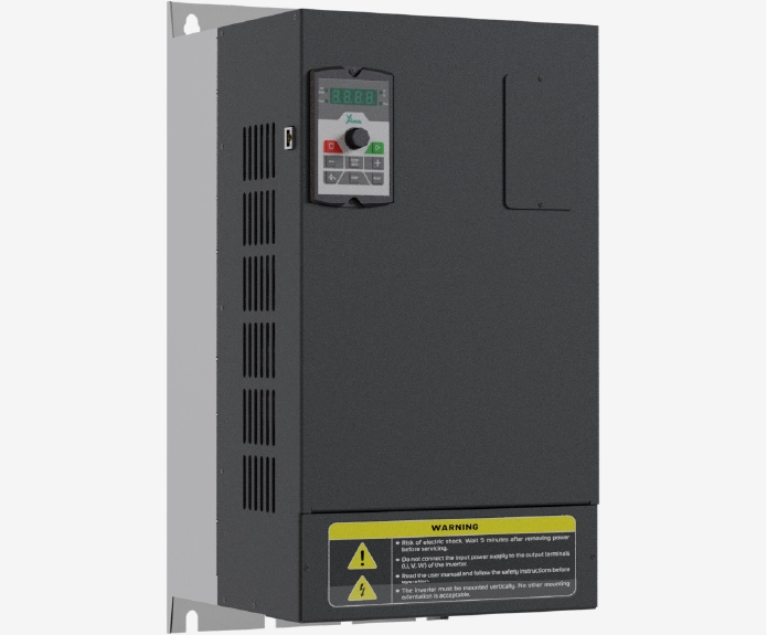
اینورتر 55 کیلووات سه فاز سری سولار پمپ
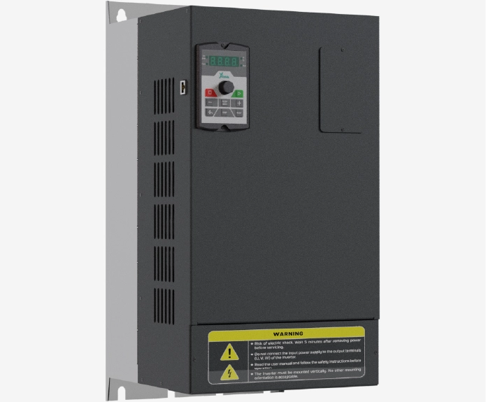
اینورتر 45 کیلووات سه فاز سری سولار پمپ
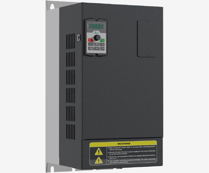
اینورتر 37 کیلووات سه فاز سری سولار پمپ
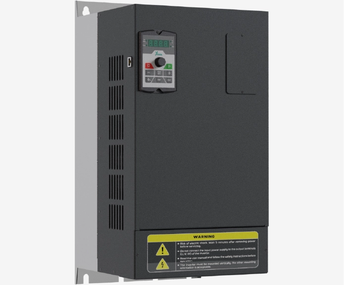
اینورتر 55 کیلووات سه فاز سری صنعتی
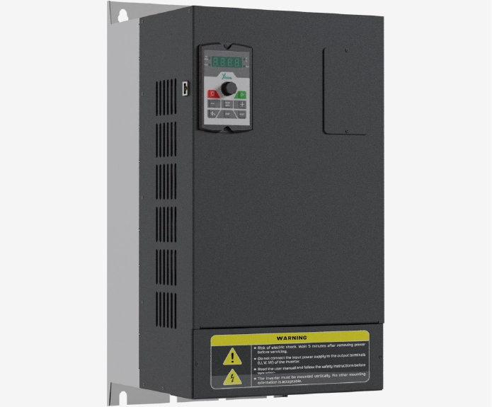
اینورتر 45 کیلووات سه فاز سری صنعتی
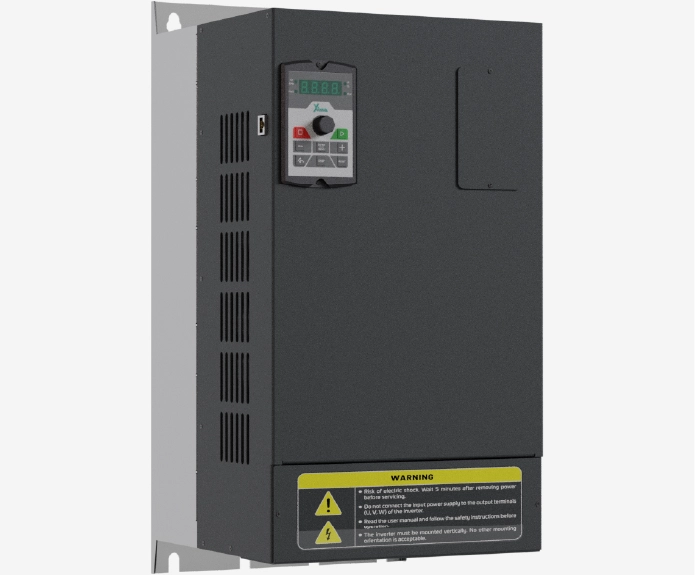
اینورتر 37 کیلووات سه فاز سری صنعتی
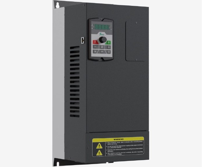
اینورتر 30 کیلووات سه فاز سری سولار پمپ
User Comments
Comments
No comments yet.